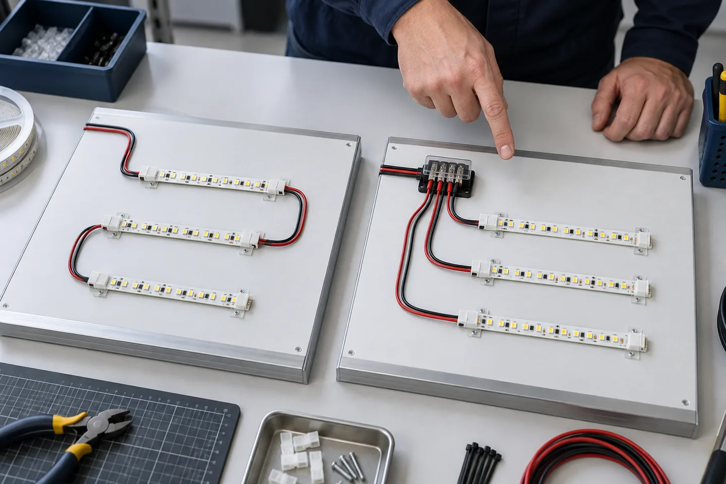
The direct answer
Both descriptions can be true, but they refer to different levels of the circuit.
- Inside a constant-voltage LED strip, LEDs are commonly arranged in small series groups. Many groups connect across positive and negative copper buses, so those groups operate in parallel along the tape.
- Between separate 12V or 24V strip runs, the normal project layout is parallel branches from a suitable distribution point. Each branch receives the rated voltage.
Do not connect two 12V strips in electrical series across 24V unless the exact product and complete design explicitly support that arrangement. Small differences in load or failure behavior can divide voltage unevenly. Use a supply matched to the strip’s rated voltage.
What happens inside a cuttable strip?
A marked cut section is an electrical building block. In a basic single-color constant-voltage strip, that block may contain several LEDs in series plus current-limiting components. The number changes with rated voltage, LED type and circuit design.
The long positive and negative copper rails carry power past repeated blocks. Each block bridges those rails. Cutting at the marked point removes complete blocks without opening the circuit path inside the retained section.
On this common layout, one open LED can darken its own series block while other blocks remain on. A dark section therefore does not automatically mean that the whole positive or negative rail is open.
That description is not universal. One-LED-cut designs, COB tape, tunable-white tape, RGB products and addressable strips use different component layouts. Inspect the cut markings and model data rather than counting LEDs and guessing the circuit.
Why separate constant-voltage runs are fed in parallel
In a parallel layout, every branch connects to the same rated supply voltage. The branch currents add at the distribution point.
For each branch:
branch power (W) = watts per meter × branch length
branch current (A) = branch power ÷ rated voltage
For the supply:
total current = branch 1 current + branch 2 current + remaining branch currents
Parallel feeds make branch lengths, cables and protection easier to define. One branch can also be disconnected for service without routing its current through another strip’s PCB. The supply, controller channel, terminal block, cable and connector must all carry the relevant combined or branch current.
The word parallel does not mean every branch must share one large cable. A system can use several protected zones or drivers when distance, maintenance, controller capacity or fault isolation makes that clearer.
A daisy chain is not necessarily electrical series
Installers often call end-to-end strip connection “series wiring.” Electrically, repeated constant-voltage segments may still sit across the same two copper buses. The practical problem is that all downstream current passes through the upstream strip tracks, connector and joint.
That added current increases voltage loss and heating at weak connections. The last section may dim or change color even though every strip has the correct rated voltage on its label.
Use end-to-end connection only within the model’s tested feed arrangement and project limit. For long or high-power layouts, separate branch feeds, center feeds or planned injection points are usually easier to verify. Measure voltage at both the feed and far end under the worst intended operating state.
Worked example: three 24V branches
Assume three separate 5m branches of a 24V strip rated at 10W/m.
Each branch:
- power: 5m × 10W/m = 50W;
- current: 50W ÷ 24V = about 2.08A.
All three branches:
- strip power: 50W × 3 = 150W;
- strip current: 2.08A × 3 = about 6.25A.
This is a planning calculation, not a driver recommendation. Select the power supply from its permitted continuous load, input voltage, enclosure, temperature derating and installation instructions. Size each branch cable for its current and route length. Size the common feed and distribution hardware for the current they actually carry.
If one controller sits before the distribution point, its channel must carry the combined load. If each branch has its own controller channel, confirm the rating of every channel and the shared input.
Cases that need a different diagram
Addressable strips
Power may be distributed in parallel while data travels from one pixel or section to the next. Long layouts need a data plan as well as power injection. Connecting data lines in an arbitrary star can fail even when the power wiring is sound.
Tunable-white and RGB strips
These products share a common conductor and use separate channel conductors. “Parallel” is too vague unless the wiring schedule states common-positive or common-negative arrangement, channel order and controller limits.
Constant-current flexible modules
A constant-current driver controls current through a defined operating-voltage range. Do not replace it with a 12V or 24V constant-voltage supply because the physical product looks like flexible tape.
Mains-voltage strips
Mains strip includes a rectifier, repeated high-voltage sections and insulated connection parts. It does not follow the same cut length, probing or branch rules as low-voltage tape. Use the exact system instructions and qualified installation practice.
Mean Well’s LED power-supply Q&A explains the functional difference between constant-voltage and constant-current output. Confirm the output mode before drawing the branch layout.
What the buyer's wiring schedule should show
Before requesting a quotation, draw one line for every powered branch and record:
- selected strip model and rated voltage;
- watts per meter and installed length per branch;
- calculated branch current;
- driver and controller location;
- cable conductor size and one-way route length;
- connector and distribution-terminal ratings;
- feed, center-feed or injection points;
- channel order for RGB, RGBW or tunable-white tape;
- access point for testing and replacement;
- the allowed voltage or brightness variation.
Send the same schedule to every supplier. A total project length such as “300 meters” is not enough to size a power system. Three hundred one-meter shelf branches and six fifty-meter contours have different wiring, voltage-drop and service requirements.
Catalog & Sourcing Note
This article is prepared from our current product catalog and B2B specification workflow. Electrical, waterproofing and installation requirements vary by model and market, so confirm the final specification and approved sample before ordering.
Discuss Your Specification