The short answer
An LED strip can usually follow a gentle curve in its permitted bending direction, but it should not be sharply creased, twisted or folded across components and solder pads to force a 90-degree corner. For a square cabinet or profile corner, the most reliable method is often to cut at marked cut points and bridge the two straight sections with a short wire jumper or a compatible corner connector.
The allowable bend depends on the complete construction: PCB thickness and copper layout, LED and resistor spacing, coating or silicone body, profile, and whether the bend is made once or moves repeatedly. Ask for the model-specific bending direction and minimum radius. A number copied from another strip—even one with the same width—is not a safe specification.
Why a sharp fold can create a delayed failure
LED tape is a flexible circuit, not a soft electrical cable. Copper tracks, solder joints and component terminations sit on a thin laminate. A tight crease concentrates strain in a small area and can crack a copper track, lift a pad, damage a component joint or tear the protective coating.
The strip may still light immediately after installation. Movement, heating and cooling, adhesive pull or later service can turn a weakened track into an intermittent fault. That is why a quick power-on test is not enough evidence that a folded corner is reliable.
Flexible-circuit design guidance from Molex notes that sharp internal corners concentrate stress and make material more prone to tearing. Würth Elektronik’s flex-circuit design guide also treats bending radius as a function of flex construction and thickness. These references explain the mechanical principle; the LED strip supplier’s drawing remains necessary for the finished tape.
Avoid bending directly across:
- an LED package, resistor, IC or connector;
- a soldered wire joint or plug-in connector;
- a factory splice;
- a cut pad or area where the coverlay has been removed;
- a sealed end cap or cable entry;
- a point already damaged by removal from a surface.
Four ways to route LED strip around a corner
1. Use a smooth curve
Use a continuous strip only when the path allows a smooth arc in the permitted direction and the bend stays away from components and joints. Support the curve so the adhesive does not try to pull the tape back into a sharp corner.
This is suitable for rounded coves, circular displays and large-radius furniture details. It is not a way to hide a hard fold inside a square aluminum profile.
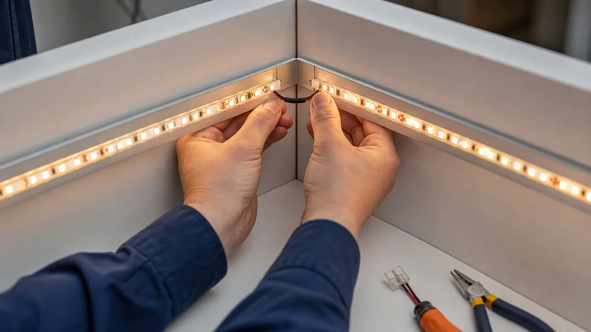
2. Cut and add a short wire jumper
For a precise 90-degree inside corner, cut both strip sections only at their marked cut points. Join corresponding pads with short flexible conductors, route the wires through the corner, and provide insulation and strain relief. The strip stays flat while the wire makes the change in direction.
Advantages:
- works where a rigid corner connector will not fit;
- allows the two profiles to meet cleanly;
- accommodates unusual pad layouts when properly soldered;
- makes the corner geometry independent of strip bending.
The joint must match the current, channel count and environment. For tunable-white, RGB or addressable tape, keep every channel and data direction correct. Use the soldering workmanship guide when specifying the jumper.
3. Use a compatible corner connector
An L-shaped or wire-style connector can speed repeatable cabinet work, but “8mm connector” is not a complete match. Check:
- PCB width and number of pads;
- pad pitch and copper-pad length;
- 2-pin, CCT, RGB, RGBW or addressable layout;
- current rating and maximum conductor size;
- indoor or protected construction;
- space available inside the profile and diffuser;
- whether the connector creates a dark gap at the corner.
Test the exact connector with the production strip. Small changes in coating thickness, pad position or PCB width tolerance can affect contact pressure.
4. Choose a purpose-built neon or side-bending construction
For continuous curves, signage and building outlines, LED neon flex can provide a more uniform luminous line and a defined bending direction. “Top bend” and “side bend” are not interchangeable. The silicone body, light-emitting face, cut interval, end cap and cable exit determine how it can turn.
Do not force a top-bending product sideways or twist it through a three-dimensional corner. Review the cross-section drawing and minimum bend radius for the exact model in the LED neon flex range, then sample the real curve and mounting channel.
Choose the method from the finished detail
| Application | Preferred starting method | What to verify |
|---|---|---|
| Square cabinet inside corner | Two straight strips plus wire jumper or compatible connector | Profile space, dark gap, joint access and door/shelf clearance |
| Rounded cove | Smooth continuous curve | Model bending direction, radius, component locations and adhesive support |
| Mitered aluminum profiles | Separate strips joined through corner wiring | Wire passage, profile edges, diffuser seam and thermal contact |
| Lettering or flowing contour | Purpose-built neon flex | Top/side bend, cut interval, end feed and mounting clips/channel |
| Outdoor building corner | Model-specific sealed joint or factory-prepared assembly | Water path, cable entry, end seal, UV exposure and service access |
| Very short furniture segment | Short-cut or one-LED-cut model | Cut interval, output, connector access and production tolerance |
For cabinet projects, the one-LED-cut SMD 2835 strip can reduce unused length near a corner because its catalog configuration allows one LED per cut. That does not remove the need for a sound joint and suitable profile.
A narrow strip can fit a smaller channel, but narrow does not mean it can accept any bend. The 3mm COB strip is listed at 3mm width and 7W/m; its allowable bend, profile and thermal conditions still need confirmation for the project.
A waterproof strip can become unprotected at the corner
Cutting an IP-rated strip changes the protective system. Exposed pads, a jumper, connector, end cap and cable entry all need a compatible sealing method. A connector marked “waterproof” does not automatically make the finished joint equal to the strip’s original IP construction.
For wet or outdoor work:
- Define whether the corner will be factory prepared or field assembled.
- Use the specified sealant, end cap, cable and curing process.
- Provide drainage and avoid creating a pocket that holds water.
- Keep the joint accessible where the design permits.
- Include the finished corner in the sample and ingress-verification plan.
- Confirm that the driver, controller and all other enclosures suit the location.
Read the IP20, IP65 and IP68 guide before treating the strip-body rating as a system rating.
Inspect corners before closing the profile
Mechanical check
- no crease, twist or bend across a component or joint;
- strip lies flat on the mounting surface on both sides;
- jumper has slack for installation but cannot be pinched by the diffuser;
- soldered wires have strain relief and insulated pads;
- connector is fully engaged and fits without lifting the strip;
- profile edges do not cut the wire or silicone body.
Electrical check
- polarity and channel order are correct;
- no copper whiskers or exposed conductors can short to the profile;
- voltage at the far section is within the model requirement under load;
- corner connector or jumper is rated for the branch current;
- all colors and dimming levels work without flicker or intermittent contact.
Appearance check
- diffuser hides the joint to the agreed viewing distance;
- corner brightness and dark gap match the approved sample;
- the luminous line does not shift position through the turn;
- reflected surfaces do not reveal exposed wires or components.
Power the assembly, operate it through the intended dimming or color sequence, and recheck after it reaches a stable temperature. Lightly moving an accessible wire can reveal an intermittent connection, but do not flex the strip repeatedly as an improvised test.
For repeat orders, send the corner drawing, profile section, strip model, connector or jumper method, IP requirement and a photograph of the finished detail through the quotation form. Approving the corner as part of the sample prevents installers from inventing a different method at each site.
Catalog & Sourcing Note
This article is prepared from our current product catalog and B2B specification workflow. Electrical, waterproofing and installation requirements vary by model and market, so confirm the final specification and approved sample before ordering.
Discuss Your Specification