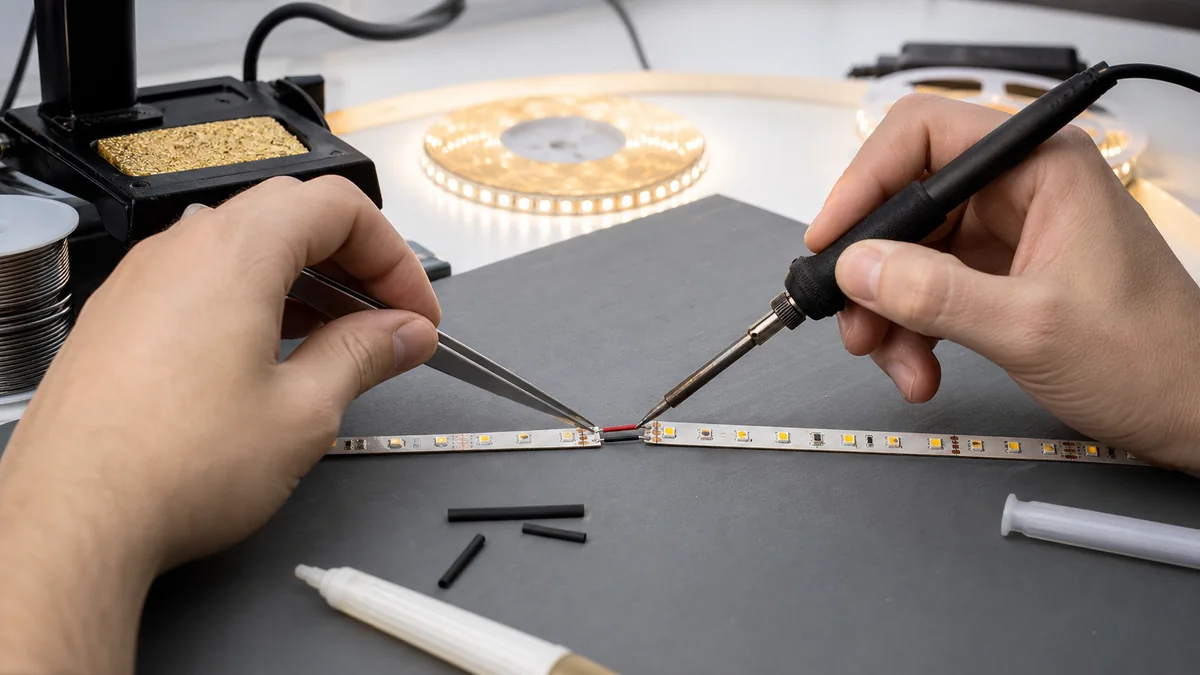
The short answer
To solder an LED strip reliably, cut only at the marked pads, disconnect all power, expose clean copper, pre-tin the pad and wire separately, make the joint quickly without moving it, then add strain relief. Match every conductor to the printed polarity or channel marking before the joint is covered.
The most common failures are not a lack of solder. They are lifted copper pads from too much heat, adjacent pads bridged by excess solder, a cold joint that moved while cooling, or a cable that pulls directly on the flexible PCB.
There is no single correct iron temperature or dwell time for every strip. Lead-free and tin-lead alloys, tip geometry, copper weight, pad size, waterproof coating and the manufacturer’s process all change the setting. Qualify the method on the exact model and record it for production.
Check these details before heating a pad
Confirm the cut point and pad layout
Cut on the printed line through the center of the exposed copper pads. If the cut leaves too little copper on one side, do not try to rescue it with a large solder blob; move to the next valid cut mark if the design permits.
Count and identify the conductors:
- single-color strips normally use positive and negative pads;
- tunable-white strips normally add separate warm- and cool-white channels;
- analog RGB and RGBW strips use a common conductor plus color channels;
- addressable strips can include power, ground and directional data pads.
Printed arrows, DI/DO, +, −, R, G, B, CW and WW are model-specific. Photograph the markings before cutting; never infer the order from wire color alone.
Choose wire for current and movement
The conductor must carry the branch current without excessive voltage drop, but it must also fit the copper pad. A cable that is electrically adequate but too stiff or heavy can peel the pad from the PCB. Use flexible stranded wire, keep the stripped length short and support the cable after the joint.
For a long feed, calculate the conductor from current and route length using the LED strip wire-gauge method. A short jumper around a cabinet corner and a ten-meter feeder do not need the same mechanical design.
Prepare the right tools
- temperature-controlled soldering iron with a clean tip suited to the pad size;
- solder and flux compatible with the approved process;
- fine cutters, wire stripper and tweezers;
- heat-resistant work surface and strip-holding fixture;
- magnification for small or multi-channel pads;
- multimeter for continuity and polarity checks;
- heat-shrink, neutral-cure sealing material or an approved joint enclosure where required;
- local fume extraction and the personal protection specified for the solder and flux.
Read the safety data for the exact consumables. Wash hands after handling solder and flux, and do not eat or drink at the bench.
A repeatable LED strip soldering method
1. Isolate and inspect
Disconnect the driver and controller. Do not solder a powered strip. Check that the cut edge is square, the pads are intact and no copper track has torn away from the flexible base.
If the strip was previously mounted, remove adhesive residue without scraping through the PCB. Keep the joint flat; bending it during soldering makes alignment harder.
2. Expose clean copper
Indoor strips usually present bare pads at each cut point. Coated and encapsulated products may require a model-specific preparation method. Remove only the material the manufacturer permits and avoid nicking copper tracks or adjacent components.
Oxidized or contaminated pads do not wet consistently. Use the approved cleaner and flux rather than compensating with prolonged heating.
3. Pre-tin the wire
Strip only enough insulation for the pad. Twist the strands neatly, apply the approved flux if required and add a small, even amount of solder. The tinned end should still fit inside the pad area without stray strands.
4. Pre-tin each copper pad
Place a small amount of solder on the pad. Use a tip large enough to transfer heat efficiently without touching nearby LEDs or components. If the pad does not wet promptly, stop and check the surface, flux, tip condition and temperature setting. Repeated heating can delaminate the pad.
Weller’s official comparison of solder joints illustrates heating the part and pad before feeding solder, then allowing the joint to cool without blowing on it. Its timing example is useful process guidance, but it is not a qualified setting for every flexible LED PCB.
5. Join the pre-tinned parts
Place the wire on the correct pad, hold it still and touch the iron to the joint only long enough for both pre-tinned surfaces to reflow together. Remove the iron, keep the wire motionless and let the joint cool naturally.
A sound joint should be compact, fully attached to the pad and free from loose strands. Its appearance varies with solder alloy, so visual shine alone is not a pass/fail rule.
6. Inspect before covering
Use magnification to check:
- no solder bridge joins adjacent pads;
- insulation does not sit inside the solder joint;
- the wire follows the intended polarity or channel;
- the copper pad has not lifted or wrinkled;
- solder has not flowed onto an LED, resistor or cut-edge track;
- the cable exits without forcing a sharp fold in the strip.
With power still disconnected, check continuity and confirm there is no unintended short between conductors. Then perform a current-limited functional test appropriate to the exact product.
7. Add strain relief
The solder joint should provide electrical connection, not carry cable weight. Secure the cable to the profile, enclosure or mounting surface so pulling and vibration do not reach the pads. Leave a gentle bend radius and avoid trapping the wire under a diffuser or end cap.
Soldering RGB, RGBW and addressable strips
Multi-channel strips need more than color-matched wires. Confirm the controller topology and the pad order on both sections.
For analog RGB or RGBW tape:
- identify whether the strip uses a common positive or common negative arrangement;
- keep channel wires in the same order through every joint;
- calculate total and per-channel current against the controller ratings;
- check for a solder bridge by testing one channel at a time.
For addressable tape:
- observe the printed data-flow arrow;
- connect controller output to the strip’s data input, not its data output;
- keep signal reference/ground continuous as required by the control design;
- follow the controller or IC supplier’s instructions for data wiring, protection and injection points.
Do not copy a connector pinout from another brand or pixel type. Two strips can look alike while using a different conductor order or control protocol.
How to handle waterproof LED strips
Cutting or opening an encapsulated strip changes the protection of that location. A joint is not IP65 or IP68 merely because the original reel carried that description.
Before ordering, specify whether connections will be factory-made or field-made. Agree on:
- where the coating or silicone may be removed;
- approved end caps, joint housings and sealing material;
- cable-entry direction and strain relief;
- curing conditions and inspection method;
- whether the finished joint needs a defined water-ingress test;
- how the seal will be serviced without damaging the strip.
Our 24V 8mm SMD2835 IP68 model has a listed silicone construction. That statement applies to the model configuration, not automatically to a site-made solder joint. Use the IP20, IP65 and IP68 guide when specifying the complete installation.
Diagnose a bad soldered connection
| Symptom | Checks to make |
|---|---|
| Joint works when pressed but not when released | Cold joint, cracked copper pad, wire movement or incomplete wetting |
| One color is missing after an RGB/RGBW joint | Wrong pad order, open channel, solder bridge or controller-channel issue |
| Connector area becomes discolored or hot | Excess current, high resistance, poor wetting, undersized conductor or inadequate contact area |
| LEDs after the joint are dim | Voltage drop in wire or joint, wrong feed layout, damaged copper track or branch overload |
| Fuse or driver protection activates | Polarity error, solder bridge, strand short or damaged cut edge |
| Outdoor joint fails after rain | Incomplete seal, cable water path, wrong material, trapped moisture or movement at the entry |
If the same joint type repeatedly overheats, stop replacing it and review branch current, conductor size, feed layout and mechanical support. The repeat-failure diagnostic guide explains how to separate a connection fault from driver, heat and voltage problems.
Buyer and production QC checklist
For repeat orders, define the connection as part of the product specification:
- strip model, cut point and pad drawing;
- wire material, conductor size, insulation and length;
- polarity or channel sequence and wire colors;
- solder alloy, flux and approved process window;
- maximum exposed conductor and joint dimensions;
- strain-relief method and pull-test requirement;
- visual criteria for bridges, lifted pads and contamination;
- continuity, polarity and functional-test method;
- sealing construction and ingress test where applicable;
- photographs of the approved sample and label orientation;
- sampling level and acceptance criteria for production inspection.
An 8mm SMD2835 120 LED/m CRI98 model and an 8mm COB 320 LED/m CRI95 model share a nominal PCB width, but their surfaces, components and cut construction are not identical. Approve the soldering method on the exact model rather than transferring settings from one family to another.
Include a joint drawing, cable specification and site environment in the quotation request. This allows the factory and installer to agree on the same connection before production starts.
Catalog & Sourcing Note
This article is prepared from our current product catalog and B2B specification workflow. Electrical, waterproofing and installation requirements vary by model and market, so confirm the final specification and approved sample before ordering.
Discuss Your Specification