The short answer
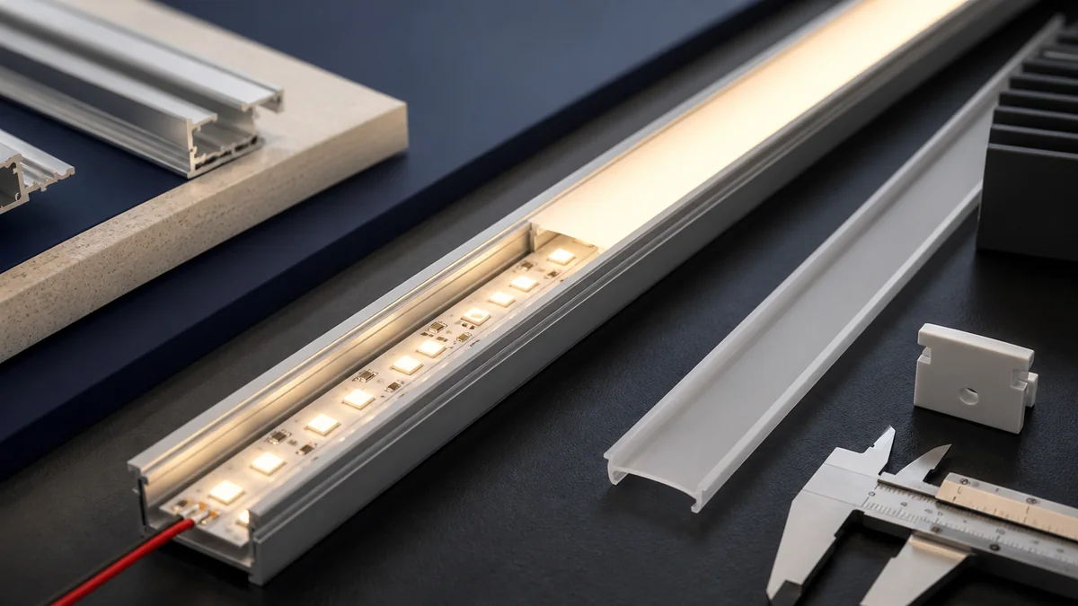
To diffuse LED strip lights, use a compatible aluminum profile with a frosted or opal cover, enough distance between the LEDs and the cover, and an LED pitch suited to that distance. A denser SMD strip or COB strip can reduce visible points, but neither guarantees a perfectly uniform line in every shallow profile.
Judge the complete assembly at the real viewing distance and angle. A line that looks smooth from across a hotel lobby may show dots in a glass display viewed from 300mm away. Camera exposure can reveal banding or hotspots that are not obvious to the eye.
LEDVANCE’s official LED strip profile guidance gives a useful starting relationship for homogeneous light: use a diffuse cover and keep the spacing between LEDs smaller than the distance from the LEDs to the cover. Treat that as a design starting point, then test the exact strip, profile and cover rather than turning it into a universal guarantee.
Why are LED dots visible?
Each SMD LED is a small source. Before light reaches the diffuser, it needs space to spread and overlap with light from neighboring LEDs. Dots remain visible when the cover is too close, the LED pitch is too wide, the cover is too clear, the viewing angle is severe, or the channel has reflective hot spots.
The main variables are:
- center-to-center LED spacing;
- distance from the emitting surface to the diffuser;
- cover diffusion and transmission;
- strip width, number of rows and position inside the channel;
- channel shape and internal reflectance;
- viewing distance and angle;
- operating brightness, CCT and camera exposure.
Do not specify “dot-free” without defining the viewing condition. It is more useful to state the closest viewing distance, expected angle, diffuser, brightness state and whether the acceptance is by eye, photograph or a measured uniformity method.
Five design decisions that improve diffusion
1. Increase the mixing distance
A deeper profile gives light more room to overlap before it reaches the cover. This is often more effective than changing only from a clear cover to a heavily frosted one. Check that the deeper profile still fits the recess, cabinet edge or cove detail.
At corners, end caps and cable entries, maintain the same optical depth. A connector standing above the PCB can push the cover up or create a shadow.
2. Reduce LED pitch or use a continuous-emitting construction
Higher LED density reduces the gap between sources, provided the strip fits the electrical and thermal design. Compare actual pitch rather than assuming that a large LED-per-meter number always means higher brightness or better efficiency.
COB strip places many small chips under a continuous phosphor layer, which usually makes a smooth line easier in shallow profiles. Still test cut points, solder joints and transitions; those areas can look different from the middle of a segment.
3. Select the cover by result, not color name
Suppliers may use terms such as clear, frosted, milky, opal or diffuse. Those names do not define one transmission value or one level of uniformity. Request the part number and optical data for the exact cover.
A stronger diffuser can hide points but may reduce delivered light. Do not compensate by automatically raising strip power. Compare the complete assembly’s output, temperature and appearance at the required task level.
4. Match strip width and profile geometry
The strip should sit flat and centered on the profile base. A narrow strip installed against one side can make the line asymmetrical. A multi-row strip may need a wider or deeper optic so the rows blend into one line rather than two or three bands.
The LEDVANCE profile catalog illustrates why profile and cover are a system: flat, medium and wide constructions use different sections and compatible accessories. Verify usable internal width, cover engagement, end caps and mounting brackets from the selected supplier’s drawing.
5. Control glare before adding more output
A perfectly smooth bright line can still be uncomfortable when directly visible. Recess the source, use an angled profile, shield the line from normal sight positions or light a surface indirectly. In cabinet lighting, check the seated or standing eye position, glossy worktops and glass shelves. In hotel coves, check the far side of the room and upper-floor views, not only the installer standing below the strip.
Should you choose COB or SMD for a diffused line?
| Project condition | Practical starting point | What still needs testing |
|---|---|---|
| Very shallow profile viewed closely | COB strip | Cut points, joint shadows, cover loss and thermal behavior |
| Deeper channel with adequate mixing distance | High-density SMD or COB | LED pitch, cover and final output |
| High output from multiple rows | Wider SMD strip and a wider/deeper optic | Row blending, temperature and glare |
| RGB or addressable effects | Compatible RGB or pixel strip | Color mixing, pixel visibility and controller scenes |
| Tight furniture detail | Narrow COB or narrow SMD model | Profile fit, cable exit and service access |
| Outdoor contour | Neon or protected linear construction | Bending direction, joints, UV, sealing and drainage |
The COB versus SMD comparison covers other purchasing differences. For diffusion alone, the correct choice is the assembly that meets the visual requirement at the lowest practical profile depth, power and complexity.
Our catalog includes an 8mm 320 LED/m COB CRI95 model and an 8mm SMD 120 LED/m CRI98 model. They should not be compared from LED count alone: approve each with the proposed profile, cover, driver and mounting detail.
A useful diffuser sample-approval test
Build a sample long enough to include a cut, joint and end cap, not only the clean center of one strip section.
- Record the strip, profile, cover, end cap, driver and controller part numbers.
- Mount the strip using the production-intent adhesive and cable exit.
- Test the maximum permitted output and every normal scene or dimming level.
- View the sample from the closest distance and most severe angle in the project drawing.
- Inspect the center, cut points, solder joints, connectors, corners and both ends.
- Compare clear and diffuse cover options only if both are valid parts for the profile.
- Measure wall input and check the strip/profile temperature after readings stabilize.
- Photograph the sample with fixed exposure if images will control production approval.
- Record the accepted result and retain a physical sample where practical.
Phone-camera auto exposure can exaggerate or hide dots. If photography, broadcast or machine vision matters, agree on camera settings or a measurable criterion before approval.
Common fixes when dots remain visible
| Observation | First change to test |
|---|---|
| Individual dots across the whole line | Deeper profile, smaller LED pitch, stronger diffuser or COB strip |
| Bright line but low task light | Review cover transmission, profile direction and target output before adding power |
| Dark mark at every joint | Shorter connector, lower-profile solder joint, aligned pads and consistent cover distance |
| Two bright bands from a multi-row strip | Wider/deeper optic or a cover designed for that channel |
| Smooth from far away but dotted up close | Define the required minimum viewing distance or redesign the profile depth |
| Diffuser bows or releases | Check compatible cover, thermal expansion, cut length and end-cap clearance |
What to put in a diffuser RFQ
- application and installation drawing;
- minimum viewing distance and likely viewing angles;
- target appearance: concealed glow, visible continuous line or high-output task light;
- strip family, voltage, W/m, PCB width, CCT, CRI and control type;
- profile cross-section and usable internal dimensions;
- cover part number, finish and available optical data;
- recess depth, cable exit, end caps, clips and joint method;
- mounting surface, ambient conditions and operating schedule;
- approval scene, viewing method and photo settings where relevant;
- acceptable component substitutions and repeat-order change control.
For a project or wholesale request, attach the profile section and a photo of the viewing position to the quotation form. That lets the supplier propose a current COB or SMD model for a real assembly instead of promising “dot-free” from LED count alone.
Catalog & Sourcing Note
This article is prepared from our current product catalog and B2B specification workflow. Electrical, waterproofing and installation requirements vary by model and market, so confirm the final specification and approved sample before ordering.
Discuss Your Specification