The short answer
To waterproof a low-voltage LED strip connection or cut end, use the termination parts and sealing process approved for that exact strip construction, assemble them on clean and dry surfaces, provide cable strain relief, allow the seal to cure as specified, and inspect or test the completed joint to the project’s requirement.
The IP marking on an untouched strip does not automatically cover a field cut. Cutting opens the jacket or encapsulation, while a splice adds conductor entries and mechanical interfaces. Treat every end cap, cable entry and connector as a separate part of the water path.
This guide covers specification and quality control for low-voltage strip systems. Mains-voltage LED strip requires its model-matched rectifier, insulation, protection and installation method, and should be handled by a qualified person under destination-market rules.
Why waterproof LED strip joints leak
Most weak points are predictable:
- the end cap does not match the strip’s finished width or height;
- silicone, coating or adhesive residue prevents full contact;
- too little sealing compound leaves a capillary path;
- too much compound prevents the cap from seating correctly;
- the cable moves before the seal cures;
- the joint is bent, pulled or crushed near the termination;
- water collects around the connection because drainage was not designed;
- the strip and connector have different claimed protection levels;
- a connector is reused after its sealing feature has been damaged.
“Waterproof connector” is not a complete specification. Record its part number, cable range, mating strip construction, assembly instructions and applicable rating. A part that fits mechanically may still be wrong for the jacket geometry or conductor arrangement.
Specify the termination before cutting the strip
Decide whether each location is a factory lead, field-cut end, inline splice, corner transition or branch. These are different assemblies and may require different parts.
For every joint, confirm:
- exact strip model and finished cross-section;
- polarity or channel order and conductor count;
- end cap, connector or cable-entry part number;
- compatible sealing material and required preparation;
- cable outside diameter and strain-relief method;
- permitted bend distance from the joint;
- curing conditions and handling time;
- inspection and test method after assembly.
The IEC 60529 IP Code classifies protection provided by enclosures under defined conditions. It does not mean that an improvised field termination inherits the rating of the original product. Ask which completed construction was assessed and whether the quoted termination is included.
Our IP20, IP65 and IP68 buyer guide explains why test conditions and model identity matter when reviewing supplier documents.
A controlled low-voltage assembly workflow
Always isolate power before cutting or connecting the strip. Then follow the exact manufacturer’s work instruction for the selected model. A practical production workflow should include these control points:
1. Cut only at the approved mark
Use a clean, square cut at the model’s stated cutting unit. A damaged jacket or angled end can prevent the cap from seating. Do not assume two strips with the same PCB width share the same cut interval or end-cap size.
2. Prepare the sealing surfaces
The mating area must be clean, dry and free from loose silicone, flux, grease and dust. Use only a cleaning method compatible with the jacket, PCB and sealing material. Let solvents evaporate fully before assembly.
3. Make and inspect the electrical connection
Verify polarity and channel order before sealing. Where soldering is specified, inspect wetting, joint size, clearance and conductor support. Where a solderless connector is specified, confirm that contacts are fully engaged and the closure is locked. The production method should match the approved sample; solder-joint controls still apply before encapsulation hides the joint.
4. Seal with the matched cap or connector
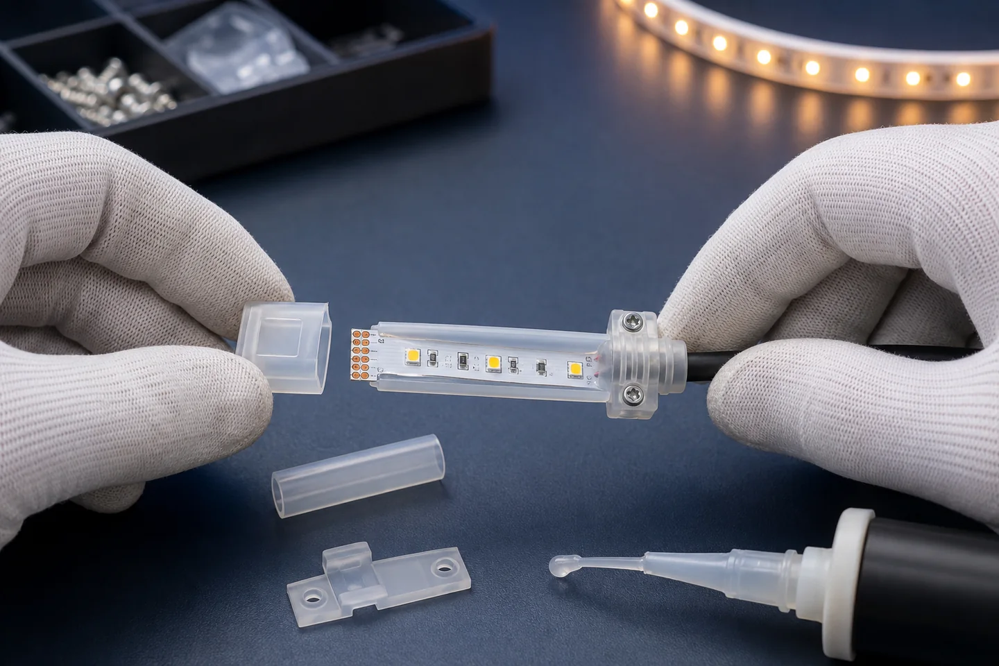
Apply the specified compound in the specified location and quantity, then seat the cap or gland without trapping an open path. Generic household silicone is not a safe substitute unless compatibility and performance have been established for the materials and environment.
5. Add strain relief and respect the cure
Support the cable so pulling and bending loads do not transfer into the conductor or seal. Hold the assembly in the required position for the full cure time. Packing or installing an uncured joint can break the seal before it has developed strength.
6. Design the installation around water
Route cable entries and joints away from standing water where possible. Provide drainage and service access in channels and junction areas. Do not rely on sealant to correct a detail that permanently traps water or pulls on the cable.
Test the finished joint, not only the reel
Electrical and sealing checks should happen in a sensible order. Confirm continuity, polarity and function before the joint is hidden. After curing, visually inspect the cap seating, seal coverage, jacket damage and strain relief.
If the project requires an ingress test, write the exposure, duration, sample state and acceptance criteria into the inspection plan. The test should represent the completed assembly, including cable entry and end cap. An untouched section from the middle of a reel does not validate a field-made joint.
Keep destructive tests separate from deliverable goods. Do not energize open connections during water exposure. For critical or regulated installations, use a competent laboratory or project-qualified test procedure rather than an improvised bucket test.
Recheck a sample after the bending, mounting and cable handling expected on site. A seal can look correct on the bench yet open after the strip is folded too close to the termination.
Waterproof connection checklist for an RFQ
Include the following with the strip enquiry:
- installation zone and expected water, dust, UV, chemical and cleaning exposure;
- required strip model, voltage, power, color and finished cross-section;
- quantity of factory leads, end caps, inline joints and corner transitions;
- cable type, length, entry direction and connector interface;
- whether cutting and termination happen at the factory or on site;
- required assembly instruction, curing controls and installer training;
- relevant test report or model-matched evidence required by the buyer;
- completed-joint inspection, sampling and acceptance method;
- channel drainage, mounting support and future service access.
For repeat orders, keep a sealed approved sample and photograph the accepted cable entry and end-cap details. If a supplier changes the jacket, cap, cable or sealant, review the termination again rather than assuming it is equivalent.
Browse the current waterproof LED strip range, then send the installation drawing and connection count with your quotation request. That gives the supplier enough information to return a model and termination plan instead of only quoting a protected reel.
Catalog & Sourcing Note
This article is prepared from our current product catalog and B2B specification workflow. Electrical, waterproofing and installation requirements vary by model and market, so confirm the final specification and approved sample before ordering.
Discuss Your Specification