The short answer
There is no single correct wire gauge for every LED strip. Choose it from the maximum current on that branch, the one-way cable length, the wire’s resistance, the permitted voltage drop, the installation method and the terminal size. For a 12V circuit, the same wattage draws twice the current of a 24V circuit, so it normally needs a larger conductor or a shorter feed cable.
Do not select 18 AWG, 20 AWG or 22 AWG from strip length alone. First calculate the branch current. Then calculate the voltage drop through both conductors in the circuit. Finally, check ampacity, insulation, local electrical rules and the connector rating. The larger conductor required by any one of those checks is the one to use.
This guide covers the low-voltage cable between a constant-voltage power supply or controller and a DC LED strip. It is not a mains-cable sizing guide.
Record four inputs before choosing a cable
1. Actual load on one branch
Use the rated watts per meter for the selected model and the meters powered by that branch:
Branch watts = strip watts per meter × powered meters
Branch current = branch watts ÷ strip voltage
Use the maximum operating load, including all active color channels. An RGB or tunable-white strip may not draw the same current in every operating state. Confirm the controller output per channel as well as the common return.
2. One-way cable length
Measure from the driver or controller to the strip input. The current travels out and back, so a two-conductor voltage-drop calculation normally uses twice the one-way length. Do not confuse a 6m route with 6m of conductor in the loop; the loop is approximately 12m before allowing for internal wiring and connections.
3. Conductor resistance
Resistance depends on conductor material, gauge, strand construction and temperature. Use the cable manufacturer’s value rather than a generic internet chart when approving a production design. Alpha Wire’s conductor chart shows why nominal resistance also differs between bare and tinned copper and between strand constructions of the same AWG.
CCA cable should not be treated as if it were copper merely because the package shows the same AWG. If the conductor material is unclear, request the construction and DC resistance in ohms per kilometer.
4. Acceptable drop at the load
The acceptable value must come from the project requirement and the operating range of the strip and controller. It may be expressed in volts or as a percentage of nominal voltage:
Voltage-drop percentage = cable voltage drop ÷ nominal voltage × 100%
A percentage that looks small on a spreadsheet still needs a physical sample check. Connectors, solder joints and the strip PCB add losses that a feed-cable calculation does not include. RGB installations also need a full-white and low-level dimming check because unequal channel drop can change color.
Calculate wire size in five steps
- Divide the project into electrical branches and record the maximum watts on each branch.
- Calculate each branch current using watts ÷ volts.
- Obtain the proposed cable’s resistance per meter from its data sheet.
- Calculate cable drop = current × resistance per meter × two × one-way length.
- Reject the size if the calculated drop exceeds the project limit, or if ampacity, temperature rating, installation rules, connector capacity or mechanical strength requires a larger cable.
The equation is a planning tool, not a final approval by itself. Lutron’s official LED tape application note illustrates that longer control-wire routes may require a larger gauge or a different layout. Its numerical tables apply to the specified Lutron system, not automatically to another manufacturer’s strip, but the design lesson is general: wire length, gauge and the connected tape load must be evaluated together.
A useful comparison before calculating
| Branch load | Current at 12V | Current at 24V |
|---|---|---|
| 30W | 2.50A | 1.25A |
| 60W | 5.00A | 2.50A |
| 96W | 8.00A | 4.00A |
These currents are arithmetic examples, not cable recommendations. They show why moving a suitable project from 12V to 24V can reduce cable drop, connector stress and distribution current. The strip, driver and controller must all use the same voltage.
Worked example: a 24V COB strip branch
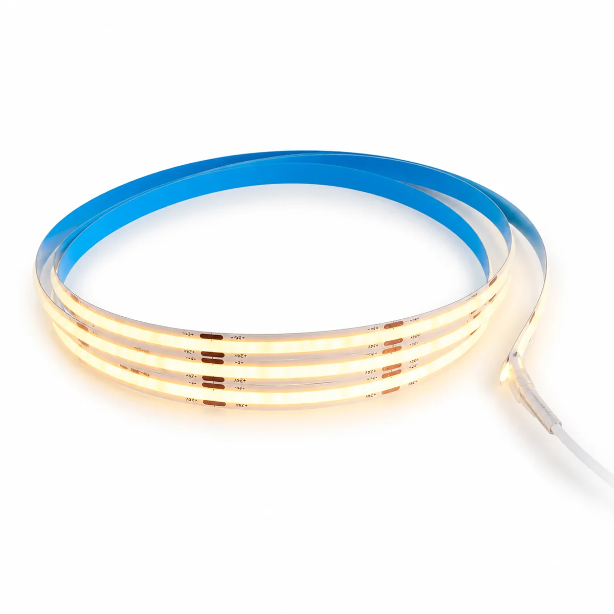
Consider 5m of our COB 8mm 320LED DC12/24V CRI95 strip, rated at 12W/m. Assume the order is configured for 24V and the one-way feed cable is 6m.
- Branch load: 12W/m × 5m = 60W
- Branch current: 60W ÷ 24V = 2.5A
- Loop length used in the cable calculation: 6m × 2 = 12m
Now obtain the actual resistance-per-meter value for each candidate cable. Multiply that value by 12m and 2.5A. Compare the result with the agreed drop limit, then add the non-calculated checks: terminal range, cable temperature rating, bundling, enclosure conditions and local code.
Do not stop after measuring 24V at the power supply. Measure at the strip input under full load and compare the far end for brightness and color. If the strip itself shows excessive drop, increasing only the feed-cable gauge will not fix the copper loss along the flexible PCB. Shorten the powered run or add correctly designed feed points. Our power-supply and voltage-drop guide explains those layouts.
How to wire multiple LED strip runs
Use parallel branches from a suitable distribution point when several runs share a power supply. Calculate each branch from the current it carries, and size the common feeder for the sum of the downstream branch currents. The power supply, distribution terminals, controller channels, connectors and protective devices must all be rated for their respective loads.
Avoid daisy-chaining several reels through the first strip or a small snap connector. That forces the upstream PCB and connector to carry current intended for every downstream run. Symptoms can include dimming at the end, color mismatch, hot connectors and intermittent operation.
For a large display or cove, a cable schedule is clearer than one headline gauge:
| Circuit item | Record on the schedule |
|---|---|
| Common feeder | Total downstream current, route length, cable specification and protection |
| Each branch | Strip model, voltage, watts, meters, current and feed method |
| Controller | Total and per-channel current limit, protocol and enclosure |
| Connections | Terminal or connector model, conductor range and current rating |
| Commissioning | Loaded voltage at supply, strip input and selected far-end test points |
Conditions that can change the answer
Cable temperature and grouping
Ampacity tables depend on insulation rating, ambient temperature, conductor count, enclosure and installation method. A cable inside thermal insulation or a crowded cabinet cannot be approved from a free-air number. Use the destination’s electrical rules and a qualified designer where required.
Terminals and connectors
A thick cable is not useful if strands are cut to force it into a small terminal. Check the published conductor range, ferrule requirements and torque. If a listed system permits a transition splice, use an appropriate enclosure and connector rather than trimming strands.
RGB, RGBW and tunable-white cable
Calculate the shared conductor and each channel for the intended control state. Confirm polarity and channel order before production. Long multichannel routes can develop unequal voltage drop, creating color variation even when total brightness seems acceptable.
Waterproof and outdoor work
The cable jacket, joint, gland, connector and enclosure need an environmental rating suitable for the installed location. An IP-rated strip does not make an unsealed splice waterproof. Plan strain relief and drainage, and avoid locating a joint where water can remain around it.
Approval by measurement
Prototype the longest and highest-load branch. Operate it until temperatures and output stabilize, then record voltage at the supply terminals, strip input and far end. Check the worst control state. A clamp meter, calibrated multimeter and thermal measurement are more useful than judging brightness by eye alone.
What to send with an LED strip RFQ
To receive a usable cable and feed recommendation, send:
- exact strip model or required voltage, watts per meter and color system;
- powered length per branch, not only total project meters;
- one-way distance from driver or controller to every strip input;
- proposed conductor material, gauge or cross-section and resistance data;
- indoor, outdoor, concealed, enclosed or high-temperature conditions;
- controller protocol and per-channel layout;
- project voltage-drop or visual-uniformity requirement;
- destination and any applicable cable or installation standard;
- connector, joint and enclosure preference;
- a simple drawing showing driver, controller, branches and feed points.
Use the 12V and 24V LED strip range to shortlist the load and voltage first. For a model-matched review, attach the circuit drawing to the project quotation form. The final cable approval remains part of the complete electrical design and local compliance review.
Catalog & Sourcing Note
This article is prepared from our current product catalog and B2B specification workflow. Electrical, waterproofing and installation requirements vary by model and market, so confirm the final specification and approved sample before ordering.
Discuss Your Specification