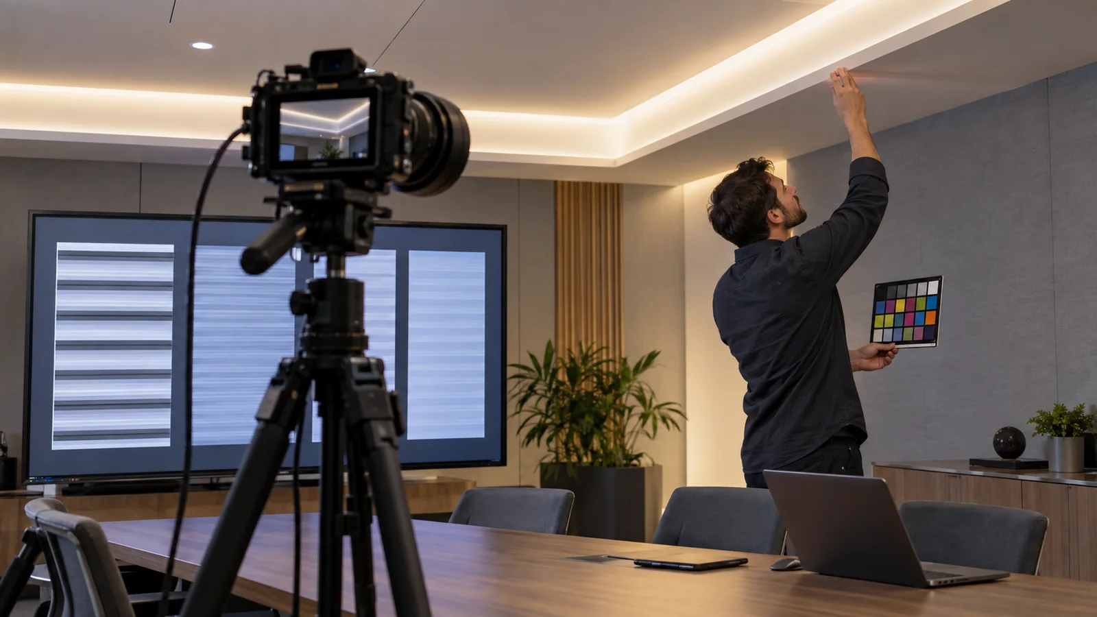
The camera is sampling a changing light output
LED strip lighting can look steady to a person and still produce dark bands, brightness pumping or color shifts on video. The camera’s exposure timing may interact with light-output modulation from the power supply or dimmer. A rolling-shutter sensor can record different parts of the frame at different moments, turning that interaction into horizontal or moving bands.
Camera suitability belongs to the complete lighting chain: strip, driver, controller or dimmer, wiring and operating level. High CRI and a dot-free emitting surface do not measure temporal performance. Test the proposed system with the cameras, frame rates and shutter settings used in the room.
This matters in conference rooms, retail livestream areas, studios, video walls, training rooms and hospitality spaces where guests record on phones. The camera test belongs in sample approval, before the profile and power equipment are repeated across the project.
Why a phone or video camera sees bands
LEDs respond quickly to changes in current. The driver and dimming method determine whether the light output stays nearly steady or varies over time. The U.S. Department of Energy’s flicker research overview explains that LED output can follow many waveform shapes, modulation depths, duty cycles and frequencies.
Camera behavior adds another variable. A Signify technical Q&A on temporal light artifacts notes that banding depends on the camera’s shutter type, shutter speed, frame rate and sensor technology, as well as the light modulation. One phone test at one automatic exposure setting cannot approve every recording condition.
Common causes include:
- a power supply with large output ripple;
- pulse-width dimming that interacts with the camera exposure;
- a phase-cut dimmer and driver combination that is unstable at part load;
- a tunable-white or RGB controller whose channel behavior changes by scene;
- low-voltage drop or loose connections that make the system pulse;
- mixed light sources operating at different modulation patterns.
Changing shutter speed can hide the banding in one shot and is useful during diagnosis. A meeting room still needs to accommodate the phones and cameras its users bring.
Color rendering and camera flicker need separate checks
CRI describes one part of color rendition. It does not measure temporal modulation, dimmer compatibility or camera banding. A CRI95 strip can still flicker when paired with an unsuitable driver or controller. A low-flicker system can also render skin, fabric or merchandise poorly.
The Illuminating Engineering Society lists ANSI/IES TM-30-24 as its method for evaluating light-source color rendition. For professional television work, the European Broadcasting Union publishes TLCI and luminaire matching guidance to help assess how light sources reproduce color for cameras.
For a standard video conference room, buyers may not need a broadcast laboratory report. They still need a visual camera test with skin tones, white and gray materials, saturated colors and the actual wall finishes. Lock the camera white balance during comparisons. Auto white balance can conceal a difference between samples or introduce a changing color cast during a call.
The 8mm CRI95 COB model is a relevant color-quality candidate from the current catalog. Its published CRI does not establish camera performance. The driver, controller, dimming level and complete scene must be approved together.
Build a repeatable camera test before bulk release
Install a representative length in the proposed profile and diffuser. Use the final driver model, cable length and dimmer or controller. Include other room lights that will operate at the same time because mixed sources can create a result that was absent in a single-fixture bench test.
Record the following combinations:
| Test variable | Minimum comparison |
|---|---|
| Camera | Main room camera plus at least one common phone class used by the client |
| Frame rate | Every project recording or call setting that matters |
| Shutter | Normal approved setting and any required alternate setting |
| Dimming | Full output, normal scene level and the lowest permitted level |
| CCT/channel | Every approved white scene; test color channels when they will be used on camera |
| Movement | Static face and hand movement or another moving subject |
| Background | Light wall, dark wall and any video display within the frame |
Use manual exposure and white balance for the controlled comparison, then repeat in the normal automatic mode that users will encounter. Watch the live image and the recorded file. Some artifacts become clearer after compression or on another display.
Label each clip with the sample ID, driver, controller, dimming level, camera, frame rate and shutter. Without those details, a supplier cannot reproduce a failed result and the buyer cannot confirm that production matches the approved sample.
Write camera performance into the RFQ
State the room use, required color temperature, color-rendering target, strip voltage and power, profile, diffuser and maximum run. Then add the recording conditions:
- camera model or camera class;
- frame rates and shutter settings to be supported;
- mains frequency at the installation location;
- dimming range and normal scene level;
- controller and driver models;
- acceptance method for visible banding, pumping and color instability;
- approved sample identification and change-control rule.
If the supplier changes the driver, controller firmware, LED package, strip circuit or dimming method, repeat the relevant camera test. A change that leaves voltage and watts per meter unchanged can still alter temporal behavior.
Troubleshoot in a controlled order
First, test the light at full output with dimming bypassed only when the equipment instructions permit that configuration. If the image becomes stable, examine the dimmer or controller and its compatibility with the driver. If the problem remains, test a known suitable driver of the correct voltage and capacity.
Next, measure voltage at the driver and strip under load, inspect terminals and compare a short sample with the installed run. A stable short sample and unstable long run point toward wiring, connections or load behavior. If two cameras show different results, keep the lighting setup fixed and compare frame rate, shutter and sensor behavior.
Use the project’s agreed test matrix as the acceptance evidence; a slow-motion phone clip covers only one camera setup. The DOE’s research page specifically notes that a metric predicting visibility for an average observer does not necessarily predict a video camera’s response.
Send the intended camera and control conditions through the quotation page when requesting a sample. LEDStripStar can confirm available strip configurations by model; the final driver, control and acceptance test must be agreed before ordering.
The header image illustrates a camera test setup. It is not a laboratory result or a record from a customer project.
Catalog & Sourcing Note
This article is prepared from our current product catalog and B2B specification workflow. Electrical, waterproofing and installation requirements vary by model and market, so confirm the final specification and approved sample before ordering.
Discuss Your Specification