The short answer
LED strip lights are not automatically a fire hazard, but an unsafe system can overheat or fail. The main risks are a mismatched power supply, overloaded cable or controller, high-resistance joints, short circuits, poor heat transfer, unsuitable mounting materials and unprotected mains connections.
Low voltage does not mean “no risk.” A 12V or 24V circuit can still carry substantial current. The driver also connects to mains power, and high-voltage LED tape brings mains potential along the strip. Selection, installation and protection must follow the product instructions and the electrical rules at the project location.
Switch the system off and isolate it immediately if there is smoke, a burnt smell, melted insulation, a browned connector, visible arcing, repeated protection trips or unexpected concentrated heat. Mains-side inspection belongs to a qualified electrician.
Where LED strip fire risk actually comes from
1. Wrong voltage or driver type
A 12V strip connected to 24V can be severely overdriven. A constant-voltage strip also needs a compatible constant-voltage driver and controller. Confirm the markings on the reel, driver and control equipment before energizing; do not rely only on an outer-carton description.
The driver should be selected from its own data sheet, including rated load, derating, protection behavior, input requirements and permitted enclosure conditions. “120W” alone is not a safety specification.
UL Solutions describes power supplies as a safety-critical part of the complete product system and identifies standards according to the equipment category and market. Its power-supply testing overview is useful context, but the applicable standard must be confirmed for the actual product and destination.
2. Excess current in wires, tracks or controllers
At equal power, a 12V system draws twice the current of a 24V system. High current increases voltage drop and heating at resistive points. Every branch conductor, connector, PCB path, controller channel and distribution terminal must be rated for the current it carries.
A larger driver does not make an undersized branch safe. Divide the installation into designed circuits and provide the overcurrent protection required by local rules and the equipment instructions. Use the power-supply and voltage-drop calculation and then check the protective-device design with the project electrician.
3. Loose or poor electrical connections
A weak crimp, loose screw, stray wire strand or poor solder joint can create a localized resistance that runs much hotter than the rest of the strip. An NFPA-hosted technical report on loose DC connections discusses how loose connections can form high-temperature points. The report is research input to code work, not a claim that every low-voltage LED joint behaves the same way.
Specify connector current ratings, conductor preparation, tightening requirements, solder criteria and strain relief. If a connector is visibly discolored, replace it only after correcting the cause.
4. Heat is trapped
LED strips release heat during normal operation. Temperature rises when power density is high, the PCB has poor contact with its mounting surface, the strip is enclosed, the driver shares a tight cavity or an encapsulated construction changes the thermal path.
Do not operate a tightly wound reel at full load unless the manufacturer explicitly permits it. Adjacent turns heat one another and the inner layers cannot release heat as they would in the intended installation.
Our catalog illustrates why model details matter: the 8mm COB 320 LED/m CRI95 strip is listed at 12W/m, while the 20mm three-row SMD 360 LED/m strip is listed at 30W/m. Their mounting and thermal reviews cannot be assumed identical.
5. The installation surface or enclosure is unsuitable
A thermally poor or combustible surface deserves a model-specific mounting review. An aluminum profile can provide a stable base, heat spreading and physical protection, but it must be sized and installed for the selected strip. Avoid contact with insulation, fabric, paper, foam or stored goods unless the complete assembly is specifically designed and approved for that condition.
Keep drivers accessible and ventilated as their instructions require. Do not bury a non-rated driver in insulation or a sealed void.
6. Water reaches an electrical joint
Moisture can corrode conductors and change connection resistance. The strip’s IP construction does not automatically cover field-cut ends, connectors, cable entries, controllers or the power supply.
For outdoor work, specify drainage, condensation control, joint sealing, cable-entry direction and enclosure ratings. The IP20, IP65 and IP68 guide explains why the whole system must be reviewed.
Low-voltage and high-voltage strips need different controls
| System | Main design focus | Important limitation |
|---|---|---|
| 12V DC | Higher current for a given power, cable drop, branch protection and short cut intervals | Low voltage can still overheat a poor joint or undersized conductor |
| 24V DC | Driver compatibility, feed layout, controller current and thermal design | Reduced current versus 12V at equal power does not remove protection requirements |
| Mains-voltage tape | Insulation, rectifier/plug set, cut and termination system, earthing where applicable, accessibility and local code | Installation and service must be handled as a mains-voltage system |
Use the 12V, 24V and 220V comparison to choose the system architecture. Do not substitute one voltage because a matching driver or plug is temporarily unavailable at site.
In North American projects, a Class 2 circuit can be relevant to some low-voltage lighting systems, but the classification and permitted load must be verified for the listed supply and connected equipment. It should not be treated as a universal international label or as permission to ignore wiring rules.
Warning signs that need action
| Observation | What it may indicate | Immediate response |
|---|---|---|
| Burnt smell, smoke or melted insulation | Severe overheating, short circuit or failing component | Isolate power; do not re-energize until inspected |
| One connector is much hotter than the strip | High contact resistance or excessive current | Isolate and inspect the joint, conductor and branch load |
| Driver repeatedly cycles off and on | Overload, short circuit, overtemperature or model-specific protection | Stop repeated cycling; identify the protection condition from the exact data sheet |
| Adhesive softens or PCB discolors | Excess temperature or unsuitable mounting condition | Isolate and review power, contact, enclosure and mounting surface |
| Fuse or breaker operates | Short circuit, overload or protective-device issue | Do not bypass or increase the rating without a qualified redesign |
| Outdoor joint shows corrosion or water | Seal or enclosure failure | Isolate, dry safely and rebuild the protection system |
| Far end is dim while feed end is hot | Excessive branch current and voltage drop | Redesign feed points and conductor sizing; do not raise voltage blindly |
Warmth alone does not establish danger, and touch is not a measurement method. The LED strip heat guide explains how to define measurement points and qualify the real assembly.
A project safety review before installation
Electrical design
- Record the exact strip voltage, watts per meter and maximum powered length per feed.
- Calculate current for each branch, not only total project wattage.
- Check driver, controller, connector and conductor ratings independently.
- Define distribution, isolation and overcurrent protection according to local rules.
- Verify voltage at the strip under load without exceeding the model limits.
- Keep mains and low-voltage wiring separated and enclosed as required.
Thermal and mechanical design
- Test the strip on the intended profile or surface, not on a reel.
- Include diffuser, enclosure, nearby driver and worst credible ambient condition.
- Secure cables so they cannot peel pads or loosen terminals.
- Keep the strip flat, away from sharp edges and within its bend limits.
- Check driver access, ventilation and replacement clearance.
Commissioning
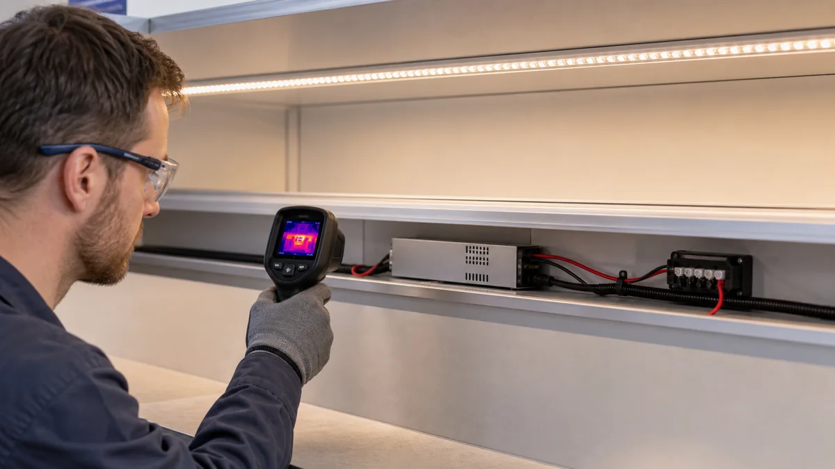
Operate the maximum permitted load state long enough for readings to stabilize. Record input and output values, temperatures at defined points, far-end behavior and connector condition. An infrared camera can help find patterns, but reflective aluminum and translucent silicone can distort readings; agree on the measurement method before using it for acceptance.
Inspect again after the installation has experienced normal operating cycles. A connection that is cool during a brief demonstration can still loosen or heat under sustained load.
LED strip fire-safety buyer checklist
Before approving a sample or order, record:
- destination country and applicable installation rules;
- exact strip model, voltage, power, PCB width and IP construction;
- driver and controller models, load per unit and derating conditions;
- length and current of every electrical branch;
- conductor size, cable route and connector current rating;
- overcurrent, isolation and enclosure plan from the project electrician;
- profile, diffuser, mounting surface and enclosure drawing;
- ambient range, operating schedule and maximum control state;
- cut-end, joint, cable-entry and strain-relief construction;
- thermal test method, measurement points and agreed limits;
- model identity, electrical ratings and conditions of use;
- commissioning record and maintenance inspection plan.
For a new project, compare the 12V and 24V product range and waterproof strip range, then attach the electrical layout and mounting section to the quotation request. Product selection is only one part of fire-risk control; the driver, wiring, protection, mounting and installation workmanship must be designed together.
Catalog & Sourcing Note
This article is prepared from our current product catalog and B2B specification workflow. Electrical, waterproofing and installation requirements vary by model and market, so confirm the final specification and approved sample before ordering.
Discuss Your Specification