The short answer
An LED strip that repeatedly “burns out” usually has a system problem, not a run of bad luck. The first checks are supply voltage at the strip, driver and controller compatibility, heat transfer, connection quality, feed layout and moisture protection. Replacing only the tape can reproduce the same failure because the cause remains in the installation.
Stop using the circuit if there is smoke, a burnt smell, melted insulation, a discolored connector or exposed mains wiring. A qualified electrician should isolate and inspect mains-fed equipment. The steps below are for diagnosing the low-voltage side and documenting a failure; they are not instructions to work on a live AC circuit.
First confirm what “burned out” means
Different symptoms point to different causes. Before cutting out a section, record a short video and note whether the fault affects one cut segment, the far end, the whole run or several branches.
- One dark group of LEDs: a damaged cut segment, copper pad, component or local solder joint is more likely than a failed driver.
- The whole run switches off and later returns: the driver or controller may be entering a protection mode. A model-specific driver data sheet is needed to interpret that behavior.
- The far end is dim but the feed end works: voltage drop is more likely than burned LEDs.
- One connector is brown or distorted: high contact resistance, insufficient current rating or poor termination needs attention.
- The strip still lights but has shifted color or lost output: prolonged heat, electrical stress or environmental damage may be involved.
- Only an outdoor splice fails: examine the cable entry, end seal and water path rather than judging the strip’s IP label alone.
A protection cycle is not proof that a strip is defective. For example, the official Mean Well PWM-120 data sheet lists different responses for overload, short circuit, overvoltage and overtemperature, and some behavior differs by model. Check the exact driver, not a generic summary.
Six common causes of repeat LED strip failure
1. The voltage is wrong at the strip
A 12V strip and a 24V strip are not interchangeable. The label on the carton is not enough: confirm the reel marking, driver output and controller output before energizing. If an adjustable supply is used, measure at the strip terminals under load and stay within the limits stated for the selected model.
Do not raise supply voltage to brighten a dim far end. That can overdrive the LEDs closest to the feed while the remote section still suffers cable and PCB loss. Correct the feed-point and voltage-drop design instead.
2. The driver or controller is undersized or incompatible
Calculate the connected strip load from the specified watts per meter and actual powered length, then include the driver manufacturer’s required operating margin and derating conditions. Check the controller’s per-channel and total current limits as separate items. A driver that cycles, a controller that overheats or a connector operated above its rating can all appear to be a strip failure.
Dimming method matters too. A constant-voltage strip needs a compatible constant-voltage supply and control arrangement. Review the control chain using our LED strip dimming compatibility guide.
3. Heat cannot leave the PCB
LEDs create heat in normal service. A high-power strip on wood, foam, fabric or an uneven painted surface can run substantially differently from the same strip mounted flat in a suitable aluminum profile. Tight enclosures, nearby drivers and full-power operation raise the thermal burden.
Cree LED’s thermal-management application note explains how junction temperature affects LED output, color, voltage and reliability. It is component-level guidance rather than a temperature limit for every tape, so acceptance must use the data for the exact strip and assembly.
As a real catalog comparison, our 8mm COB 320 LED/m CRI95 strip is listed at 12W/m, while the 20mm three-row SMD 360 LED/m strip is listed at 30W/m. Those products need different thermal reviews; LED count alone does not predict temperature.
4. A joint or connector has high resistance
A loose screw, partially inserted conductor, cracked solder joint or connector with too little contact area can create a concentrated hot spot. This often leaves local discoloration while the rest of the strip looks normal. Check current rating, conductor preparation, polarity, solder wetting, strain relief and whether the connector is approved for the PCB width and coating.
5. The branch is too long or fed incorrectly
Long daisy-chained runs carry the combined branch current through the first section. That increases voltage drop and stresses copper tracks and early connectors. Specify the maximum powered length per feed for the exact model, then use additional feeds or parallel branches where required. Cable size should be calculated from current, route length and acceptable drop; the LED strip wire-gauge guide shows the method.
6. Water protection is incomplete
An IP-rated strip is only one part of an outdoor system. Cut ends, joints, connectors, cable entries and the driver enclosure must suit the exposure and installation method. Trapped condensation and water following a cable into an end seal can cause corrosion or intermittent faults.
Our catalog includes an 8mm 24V SMD2835 model with a listed IP68 silicone construction. Its rating must not be transferred to field-made joints or other models. Use the IP20, IP65 and IP68 selection guide to define the complete construction.
Use the failure pattern to narrow the cause
| What you observe | Checks to make first |
|---|---|
| Failures start near the power feed | Actual input voltage, first-section current, connector temperature and branch layout |
| Several random cut segments fail | Operating temperature, driver output, handling damage, batch history and environmental exposure |
| The driver repeatedly shuts down | Connected load, short circuit, controller wiring, ventilation and model-specific protection behavior |
| The far end dims or changes color | Voltage drop, wire size, maximum feed length and PCB current path |
| Failure appears after installation in a profile | PCB contact, pinching at end caps, screw heads, sharp bends and trapped heat |
| Outdoor failure begins at a cut or joint | Seal method, cable entry orientation, condensation, connector rating and drainage |
| Adhesive lifts before LEDs fail | Mounting temperature, surface preparation, thermal load and cable strain |
Do not diagnose from the damaged part alone. Compare it with an unused sample from the same lot and with a working branch under the same load. That comparison often exposes a wiring or installation difference.
A safe, repeatable test sequence
- Isolate power and identify every component. Record strip model, voltage, watts per meter, length, driver, controller, connectors and wire sizes.
- Inspect without power. Look for reversed polarity, crushed PCB, copper exposed by a screw, poor soldering, moisture paths and browned plastic.
- Separate the loads. With the system isolated, disconnect branches so a short or overload can be located without repeatedly energizing the complete installation.
- Check low-voltage output under controlled conditions. A competent technician should compare the measured driver output with the exact strip specification, both without load where appropriate and under the intended load.
- Measure current and power. Compare them with the calculated load and the ratings of the driver, controller, connectors and conductors.
- Operate the strip fully unrolled on its intended mounting surface. Never full-power a tightly wound reel unless the product instructions explicitly allow it.
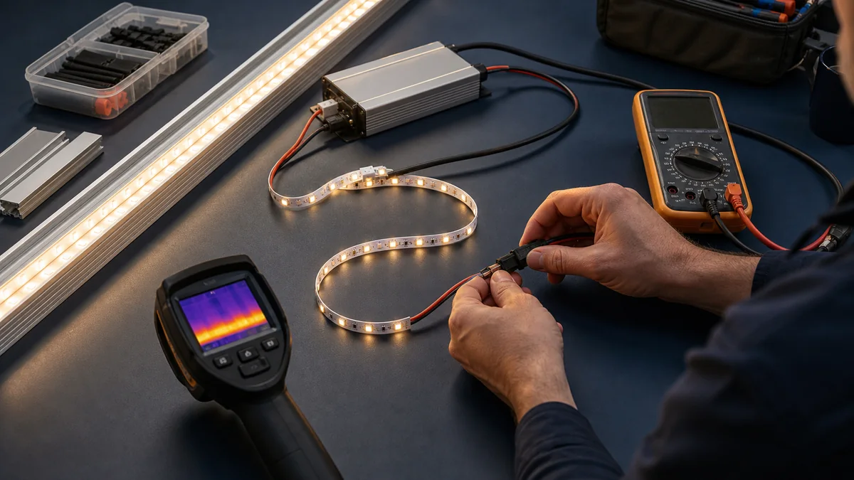
- Map temperature and voltage. Use defined measurement points at the feed, joints, middle and far end. An infrared image can locate patterns, but reflective metal and silicone can distort readings.
- Change one variable at a time. Replacing the driver, cable and strip simultaneously may restore light but will not prove the root cause.
Keep the failed section, driver label, wiring drawing, photos and readings. This evidence lets the installer and supplier investigate the same system rather than trade guesses.
Prevent the same fault in production
Approve a complete assembly, not a loose reel on a desk. The trial should use the production-intent profile, diffuser, adhesive, driver, controller, connector, cable, feed length and enclosure. Run the highest permitted load state in the worst credible ambient condition until readings stabilize.
For a repeat project, create a short approval record:
- exact model and batch identification;
- wiring diagram and maximum length per feed;
- driver and controller part numbers;
- mounting surface, profile and enclosure detail;
- voltage, current, power and defined temperature readings;
- photographs of joints, seals and cable entries;
- pass/fail limits taken from agreed product data;
- burn-in or sampling plan for production inspection.
Then turn the critical items into the pre-shipment inspection checklist. A carton label can confirm voltage and model, but it cannot replace an electrical and thermal check on the approved configuration.
What to send when asking a supplier for help
- model code, rated voltage, watts per meter and IP construction;
- powered length per feed and total quantity per driver;
- driver, controller and connector labels;
- cable size and one-way distance to each feed;
- mounting material, profile drawing, diffuser and enclosure;
- ambient conditions and daily operating schedule;
- when the failure began and how many sections are affected;
- clear photos of the feed, failed area, joints and end seals;
- low-voltage readings taken by a qualified technician;
- whether the failure follows one batch, one driver or one location.
If you are selecting a new system, compare the COB strip range and SMD strip range by voltage, power, PCB width and construction. Include the proposed wiring and mounting details in the quotation request. That gives us enough information to recommend a configuration and sample test instead of substituting a new reel into an unresolved fault.
Catalog & Sourcing Note
This article is prepared from our current product catalog and B2B specification workflow. Electrical, waterproofing and installation requirements vary by model and market, so confirm the final specification and approved sample before ordering.
Discuss Your Specification