The short answer
Most low-voltage constant-voltage LED strips can be dimmed, but not by any dimmer. The strip voltage, color type, channel count, controller output, power-supply loading and control protocol must work as one system.
A single-color 24V strip may use a PWM controller between a fixed 24V power supply and the strip. Another project may use a purpose-built dimmable constant-voltage driver controlled by phase-cut, 0/1–10V, DALI or another building-control signal. RGB, tunable-white and addressable strips need controllers made for their channel or data arrangement.
Do not connect a low-voltage strip directly to a mains wall dimmer. A qualified person should design and connect mains wiring, and every component must be approved for the selected control method.
Two common ways to dim a low-voltage LED strip
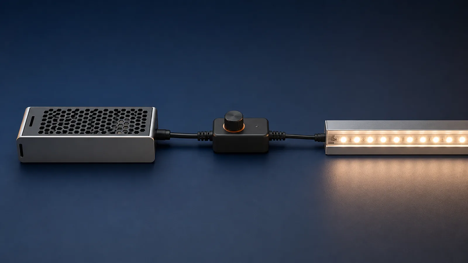
Fixed-voltage power supply plus a DC-side controller
The component order is:
AC supply → fixed constant-voltage power supply → PWM controller → LED strip
The power supply provides the strip’s rated DC voltage. The controller rapidly switches its output to adjust average light level. Lutron’s PWM and CCR application note explains the PWM principle: the ratio of on time to off time controls perceived brightness. The note focuses mainly on constant-current systems, and it specifically observes that constant-voltage LED drivers are primarily PWM dimming drivers.
This architecture is common for single-color, tunable-white and RGB strip systems. The controller still has to match the voltage, channel arrangement and current on every output.
Dimmable constant-voltage driver
The component order is generally:
AC supply and approved control signal → dimmable constant-voltage driver → compatible LED strip
The driver accepts a specified interface. For example, LEDVANCE lists constant-voltage outdoor drivers with a 1–10V dimming interface. This shows why “dimmable” is incomplete without the interface and exact driver model.
Do not assume a phase-cut wall control can operate a 1–10V driver, or that a non-dimmable power supply will behave correctly behind a wall dimmer. Use the driver’s compatibility information and approved control list where one is provided.
Match the controller to the strip type
| Strip type | Typical control need | What must be confirmed |
|---|---|---|
| Single-color white | One output channel | Strip voltage, branch current, controller polarity and dimming range |
| CCT tunable white | Two coordinated white channels | Common connection, channel current, CCT-control method and full-load state |
| RGB | Three color channels | Pinout, common polarity, per-channel and total controller ratings |
| RGBW | Four color channels | RGBW pinout, white-channel load, total power and control scenes |
| Addressable or “magic” strip | Data controller matched to the strip IC | Supply voltage, data protocol, pixel grouping, data direction and injection plan |
| High-voltage strip | Product-specific mains control system | Approved dimmer, rectifier/controller, minimum load and regional electrical rules |
Wire count alone is not a safe identification method. Two products with the same number of conductors may use different common connections, pin orders or data protocols.
Our COB 8mm 480LED CCT tunable strip and COB 12mm 720LED RGB magic strip illustrate the difference. The first requires coordinated white channels; the second is an addressable model with a specified control IC. A generic single-channel dimmer is not a substitute for either control system.
Nine compatibility checks before buying the dimmer
1. Output voltage
The strip, controller and driver output must use the same rated voltage. A controller that accepts 12–24V does not convert a 24V supply to 12V unless its specification explicitly says it is a converter.
2. Maximum load state
Calculate the watts and current for the longest powered branch at its highest permitted control state. For RGBW or tunable-white products, confirm whether multiple channels may operate together and use the manufacturer’s rated full-load condition.
The controller must meet both its total-output rating and its per-channel rating. Apply any enclosure or ambient-temperature derating stated in its data sheet.
3. Driver capacity and load range
Size the power supply from the connected load and its manufacturer’s loading instructions. Some dimmable drivers also specify a minimum load or different performance near the bottom of their load range. Our power-supply and voltage-drop guide covers branch planning without assuming one universal spare-capacity percentage.
4. Dimming interface
Write down the actual interface: rotary PWM control, RF, Bluetooth, Zigbee, phase-cut, 0/1–10V, DALI, DMX or another protocol. A marketing label such as “smart” does not establish compatibility.
LEDVANCE’s published 24V RGBW/TW controller, for example, identifies PWM dimming, its supported strip types and its channel limits. Check the same fields for the controller actually proposed for your project.
5. Dimming range and low-end behavior
“0–100%” on a controller page does not prove that the complete system will produce a smooth, stable fade to the project’s required minimum. Test the exact driver, controller, strip length and cable layout. Record the lowest stable level and whether the strip turns on cleanly from that setting.
6. PWM frequency and the application
PWM that looks steady to the eye may still create bands on a camera or interact badly with machine vision. If the strip will be used in retail filming, studios, broadcast areas or high-speed inspection, put a measurable flicker or camera requirement in the specification. Do not approve it by phone video alone; shutter settings change the result.
7. Cable and feed layout
Voltage drop can cause uneven output, color shift or different low-end behavior along a run. Long lines should be split into branches or fed at planned points. Size the LED strip cable from current, route length and the agreed drop limit.
8. Connectors and waterproof transitions
The connector must fit the PCB width, conductor count, current and IP construction. A clip that fits an indoor 10mm RGB strip may not seal an encapsulated 10mm product. Confirm the complete transition from cable to strip, including strain relief and end sealing.
9. Power-loss behavior
For hotels, retail displays and building-control projects, decide what happens after a power interruption. The system may return off, return at full output, restore the last scene or wait for a network command. Test this behavior instead of discovering it after installation.
Why does a dimmed LED strip flicker or behave poorly?
| Symptom | First checks |
|---|---|
| Flicker only at low level | Driver minimum load, controller low-end setting, connection resistance and actual strip load |
| Flicker at every level | Supply stability, overload protection, loose connections, controller rating and incompatible control interface |
| Strip does not turn fully off | Driver leakage current, controller design, wiring and any illuminated wall control |
| Sudden jump near the bottom | Dimming curve, minimum command level and driver/controller compatibility |
| Different color during dimming | Unequal channel loading, cable drop, controller calibration and strip binning |
| Camera shows moving bands | PWM frequency, camera shutter/exposure and the project’s flicker requirement |
| Controller or connector gets hot | Current rating, terminal contact, cable preparation, enclosure and derating |
Do not raise the supply voltage to fix dimming problems at the far end. That can overdrive the section nearest the feed. Correct the branch and feed layout, then retest the full dimming range.
A sample-approval test for a commercial project
Build one representative circuit with production-intent components and cable lengths.
- Record every model number, rated voltage, firmware version where relevant, and wiring diagram.
- Measure input and output voltage, current and power at the maximum permitted load state.
- Operate the system at full output until temperatures stabilize; inspect the driver, controller, connectors and strip.
- Step through the required dimming range. Record the lowest stable level, turn-on behavior and any visible flicker or color change.
- Test every required scene, channel combination and wall or network command.
- Switch power off and on several times and confirm the required recovery state.
- Test the longest planned feed and branch, not only a short bench sample.
- For camera-critical work, use the project’s agreed measurement or camera test method.
- Seal the approved sample and retain the component list for production comparison.
The test approves that component set and layout. Replacing the driver, controller, strip IC or cable can change the result even when the replacement carries the same general description.
What to include in a dimmable LED strip RFQ
- strip model, voltage, watts per meter, meters per branch and total quantity;
- single-color, CCT, RGB, RGBW or addressable control type;
- required interface and building-control system;
- lowest required light level and expected fade behavior;
- driver and controller models, or permission for the supplier to propose them;
- maximum cable distance, feed points and connector method;
- indoor or waterproof construction and enclosure temperatures;
- camera or flicker requirement, if relevant;
- power-loss recovery state and network behavior;
- sample-approval tests and component change-control rules.
Standard LED strip MOQ is 3,000m. For a quotation, send the circuit schedule and control requirement with the strip quantity. We will match the request to current catalog models and confirm the available control and document options for the selected build rather than treating “dimmable” as a complete specification.
Catalog & Sourcing Note
This article is prepared from our current product catalog and B2B specification workflow. Electrical, waterproofing and installation requirements vary by model and market, so confirm the final specification and approved sample before ordering.
Discuss Your Specification