Cut the slot to the selected profile, not to the LED strip alone
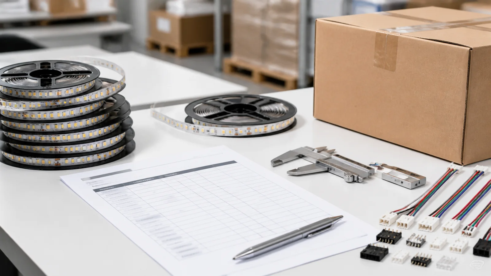
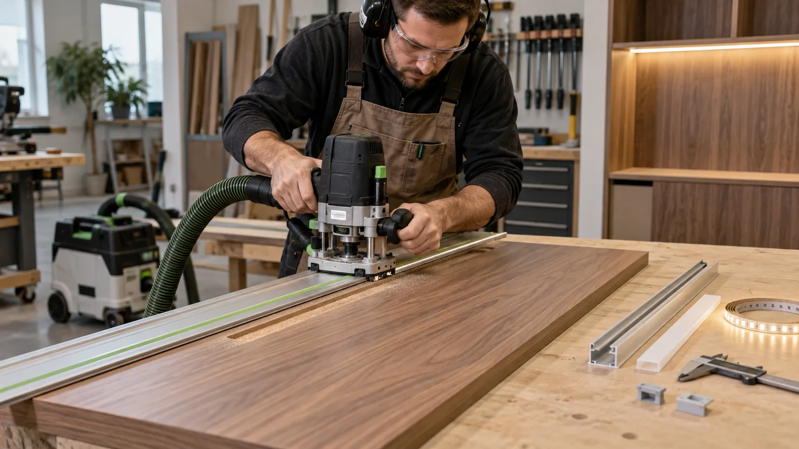
Use a recessed aluminum profile inside the routed wood slot. Measure the profile body, flange, end caps, cable outlet and diffuser before cutting production panels. The slot dimensions should come from the profile drawing and a physical sample. An 8mm LED strip does not require an 8mm groove: the profile that carries it will be wider, and its mounting method may need extra depth or clearance.
Make a full-size joinery sample first. It should include the actual board or timber, finish, profile, diffuser, strip, cable exit, driver and connector method. Check the sample from the normal viewing angle with the light both on and off. This catches loose profiles, visible LED points, reflected router marks and diffusers that cannot be removed after installation.
The finished detail has three separate fits:
- the strip must fit inside the profile without pressing against its sides or connector;
- the profile body must fit the routed slot without rocking or forcing the wood apart;
- the flange and diffuser must sit at the intended level relative to the finished surface.
Read the complete profile cross-section
Start with the manufacturer’s cross-section or CAD file. Record these dimensions:
| Item | Why it matters |
|---|---|
| Profile body width | Controls the routed slot width |
| Overall flange width | Determines the visible trim and edge cover |
| Profile body depth | Controls the minimum slot depth |
| Diffuser height and removal direction | Determines whether the cover can be fitted and serviced |
| Internal PCB width | Must clear the LED strip and any soldered joint |
| End-cap thickness | Affects the finished cut length |
| Cable outlet position | Controls drilling and concealed cable routing |
| Clip, screw or adhesive detail | May add depth or require local recesses |
Do not create a universal clearance by adding an arbitrary amount to every profile. Extrusion tolerances, wood movement, coating build-up and the fixing method differ. Use the profile supplier’s installation allowance. If none is published, cut test slots in offcuts and agree the accepted fit with the joinery contractor before releasing a production drawing.
The LEDVANCE LED strip profile brochure shows that profile families have different external and internal dimensions, covers, end caps and brackets. Häfele also lists profile-specific end caps with cable outlets. These examples explain why the joinery drawing must name the exact profile and accessories.
Flush, proud or recessed diffuser
A flush diffuser gives a clean line but exposes inaccurate routing and uneven veneer edges. A slightly recessed diffuser can reduce glare at some viewing angles. A proud diffuser changes the tactile and visual finish and may catch cleaning tools. State the intended relationship on the section drawing instead of leaving it to the router operator.
If veneer, laminate, lacquer or stone is added after routing, include the finish thickness in the detail. A groove cut correctly in the substrate may become too narrow after coating or edging.
Plan corners, cable exits and service access
Mark the complete luminous route before routing. Long cabinet runs rarely consist of one uninterrupted straight line. Doors, shelves, partitions, hardware, glass supports and appliance vents can block the profile or cable path.
For each run, identify:
- the visible start and stop points;
- the position of every profile joint;
- inside and outside corners;
- the strip cut points that can serve those dimensions;
- cable exits and strain relief;
- driver and controller access;
- removable panels needed for future replacement.
Avoid placing a profile joint directly at the main viewing position when a small layout shift can hide it. Align profile joints with shelf divisions or architectural breaks where practical. The LED strip joint and profile joint do not always have to occur at the same point; stagger them only when the profile can still be serviced and the strip is not bent or trapped.
Never route through screws, concealed brackets, dowels, hinges or structural areas without approval from the joinery designer. A deep groove near the edge of MDF or plywood can weaken the remaining section. Solid timber also moves with moisture. The joinery contractor should confirm the remaining material, edge distance and grain direction for the exact panel.
A practical routing and installation sequence
- Approve the physical profile, diffuser, end caps and strip sample.
- Transfer the profile cross-section and cable route to the joinery shop drawing.
- Mark hardware, joints and no-cut zones on the panel.
- Set the router with guides or a jig that controls width, depth and straightness.
- Cut a test slot in an offcut of the same material and finish build-up.
- Dry-fit a full profile length. Check the flange, corners, end caps and diffuser removal.
- Route the production piece using the approved setup and dust extraction.
- Drill cable exits with smooth edges and enough space for the actual lead and connector.
- Finish and clean the slot. Remove dust before fitting any adhesive-backed component.
- Install the profile without distorting it, then fit the LED strip on the clean aluminum surface.
- Support the lead so it cannot pull on the solder pads.
- Test the complete run at rated voltage before the cabinet is closed or delivered.
The LEDVANCE strip installation guide shows handling limits, marked cutting areas and profile installation examples. Use the instructions supplied with the ordered strip and profile for the project. Keep the LED reel away from routing dust and finishing work.
Select the strip after checking profile depth
The current catalog includes an 8mm COB CRI95 model and an 8mm SMD2835 CRI98 model. Both can fit profiles designed for an 8mm PCB, subject to joint and connector clearance. They will not produce the same appearance through every diffuser. Test the selected CCT, output and dimming level in the actual routed detail.
A shallow profile can show SMD points or the darker interval around a joint. A COB strip may create a smoother line, although profile depth, diffuser transmission and viewing angle still affect the result. Do not approve the strip from an open-reel photograph.
Defects to reject before production routing
The profile is tight in some areas and loose in others
Check router setup, panel flatness, coating thickness and extrusion tolerances. Forcing a profile into a tight groove can bow the profile, crack the finish or prevent diffuser installation. A loose groove may leave an uneven visible line.
The diffuser cannot be removed
Some covers snap in from the front, while others slide from an end. A wall, return panel or closed end may block the required movement. Prove the service method in the mock-up.
The cable pushes the profile upward
Increase the local cable cavity or move the outlet according to the approved section. Do not crush the lead behind the extrusion or leave it pulling on the strip pads.
Light leaks from the end
Check the end cap, profile cut and adjacent joinery. Painting over the leak makes later replacement harder. Correct the mechanical detail.
The light line is straight but the reflection is uneven
The groove may be too close to a wall, shelf edge or glossy finish. Test the intended setback and viewing angle. The router dimension controls the fixture location, while the surrounding geometry controls the reflected light.
Information for the joinery lighting RFQ
Send the strip supplier and joinery contractor the same controlled drawing. Include:
- profile brand, code and cross-section;
- strip model, PCB width, voltage, power and cut interval;
- selected diffuser and end caps;
- finished slot width, depth and diffuser level;
- panel material, surface finish and finish thickness;
- exact run lengths and joint positions;
- cable outlet diameter and direction;
- driver, dimmer and access location;
- sample quantity and full-size mock-up requirement;
- labels for each cabinet, room or run.
Allow the electrical cut interval to influence the joinery dimensions before production starts. A 1,963mm luminous line cannot always be made from a strip with a long cut unit without a short dark end or a changed cabinet detail. Send the cut list and profile section through the quote form for model matching. Standard wholesale MOQ is 500m, and the final configuration must be agreed before production.
Catalog & Sourcing Note
This article is prepared from our current product catalog and B2B specification workflow. Electrical, waterproofing and installation requirements vary by model and market, so confirm the final specification and approved sample before ordering.
Discuss Your Specification