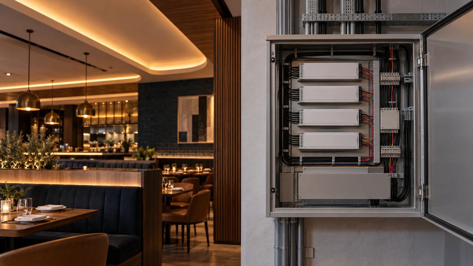
Divide the installation into documented, accessible driver zones
Plan driver replacement before closing ceilings and joinery. Each driver zone should have a known strip load, cable route, control method, location and access panel. A maintenance team must be able to isolate and replace one failed unit without opening a finished ceiling or switching off an entire floor.
The strip schedule comes first. Record exact model, voltage, watts per meter and installed length for every branch. The project electrical designer then sizes the power supplies, protection and wiring under the applicable local rules. Do not select a driver from the reel length alone.
Use zones that match rooms and service access
One large supply may reduce the number of boxes, but it can also enlarge the outage and create longer low-voltage cable runs. Several smaller zones may be easier to isolate and replace. Draw both layouts and compare the cable routes, access points and outage areas for that project.
For a restaurant, hotel or retail floor, map each driver to a visible area that staff can identify: reception counter, north cove, shelf bay 1 or terrace canopy. Avoid a zone that crosses unrelated rooms unless the cable route and access make that arrangement sensible.
Calculate connected strip load from the approved watts per meter and actual branch lengths. Allowance above the calculated load belongs in the electrical design; the driver manufacturer may specify limits that depend on temperature, enclosure and operating conditions. Driver wattage alone does not confirm the voltage delivered to the strip, so measure voltage at the far end of every branch.
A replacement must match more than voltage and watts
Record input supply, output type, output voltage, rated load, dimming interface, minimum load where relevant, enclosure, ambient limit, physical size, terminals and mounting orientation. For dimmed systems, note the exact controller and tested dimming range. A replacement with the same headline wattage can still behave differently at low output or with the installed control.
If the project uses DALI, state the required function instead of writing only “DALI driver.” The DALI Alliance device-type guidance explains that DT6 covers LED drivers while DT8 relates to color control under IEC 62386 Part 209. Tunable-white or multi-channel work needs a control schedule that matches the strip and driver arrangement.
For simple constant-voltage projects, the driver schedule still needs the dimming method, controller position and channel load. Test the proposed strip, driver and control together. The LED strip dimming guide lists the compatibility questions to settle before ordering.
Access panels need working room and ventilation
Place drivers where a technician can identify the correct unit, disconnect it safely and fit the approved replacement. Leave space for terminals, cable bend and test probes. A removable decorative panel is only useful if staff know how to open it without damaging the finish.
Check the thermal condition with the access panel in its normal closed position. A driver above a kitchen ceiling, inside a shallow cabinet or near a glazed facade can experience a different temperature from the occupied room. Follow the driver’s installation instructions for clearance and orientation.
Keep mains and extra-low-voltage wiring separated and protected as required by the project design. A qualified electrician should complete and verify the installation. The generated header image is an explanatory concept and must not be used as a wiring detail or customer-project record.
Leave a record that survives staff changes
Give every driver an identifier that matches the as-built plan and distribution-board schedule. Record the installed model, settings and connected branches. Add the cable details, controller address where applicable, commissioning date and measured operating observations. Keep a copy in the facility file because labels hidden above the ceiling are easy to lose during later work.
Photograph each accessible location before handover. For addressable or networked controls, export the final configuration and explain how a replacement device is commissioned. The DALI Alliance describes standardized luminaire, energy and diagnostics data available in specified DALI systems. Those maintenance functions depend on the selected equipment supporting them.
Choose project spares after the driver schedule is stable. Stocking one approved unit for a repeated zone can be more useful than buying several unmatched supplies. Store the mating connectors, mounting parts and configuration notes with it.
Issue the driver schedule with the strip order
List each zone, strip model, voltage, total meters, calculated connected load, branch count, longest cable route, control interface, driver location, access method and environmental condition. Identify any emergency-lighting or building-control requirement separately; it cannot be inferred from a standard strip quotation.
Send the schedule, reflected-ceiling plan and control narrative through the project quote form. LEDStripStar can confirm the written strip specifications and available models. The responsible electrical designer must approve driver sizing, protection, controls and compliance for the installed system.
Catalog & Sourcing Note
This article is prepared from our current product catalog and B2B specification workflow. Electrical, waterproofing and installation requirements vary by model and market, so confirm the final specification and approved sample before ordering.
Discuss Your Specification