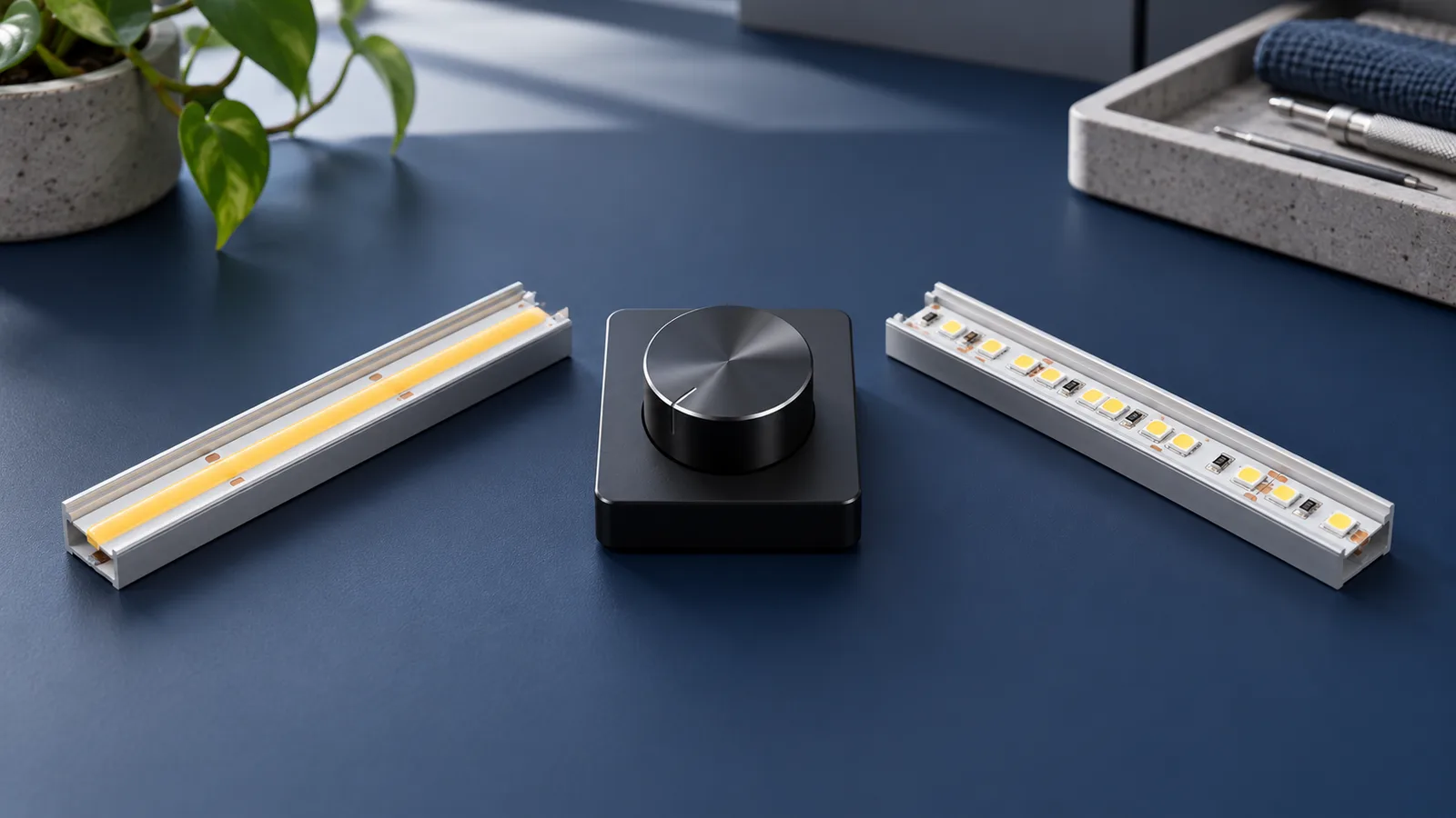
Yes, different conventional single-color LED strip models can sometimes share one low-voltage dimmer output if they use the same operating voltage, compatible control method and a combined load within all equipment ratings. They will receive the same dimming command. That does not guarantee equal brightness, matching color or the same useful dimming range.
Clarify whether the strips will share one electrical output or receive commands from one wall control through several separate outputs. Review those systems separately. This guide focuses on conventional constant-voltage strips; addressable, RGB and tunable-white systems need their own channel or protocol review.
Check what the strips would actually share
A two-wire single-color strip has a different control arrangement from an RGB strip or a tunable-white strip. Matching the remote brand, connector shape or word “dimmable” does not establish that the loads can share an output. Use the controller selection guide to identify the topology first.
For one conventional low-voltage output, record the selected voltage for every branch. Do not connect a 12V strip and a 24V strip to the same constant-voltage output. A dimmer that accepts a broad input range does not automatically give each attached strip a different voltage.
For example, Waveform Lighting’s FilmGrade dimmer page specifies an operating voltage range and a current limit, and shows placement between the supply and LED load. These are separate compatibility checks. Its published range is not permission to mix different strip voltages on one output, or evidence that an unspecified mixed installation has been approved.
If one wall control sends a command to separate drivers, each driver must suit its own strip. The control interface, permissible number of connected devices and signal wiring also need manufacturer confirmation. Never join the DC outputs of separate supplies unless their documentation expressly allows the intended arrangement.
Add all branches at their reachable maximum
Different watts per metre are not automatically a reason to reject a shared dimmer. They change the load calculation. Use the exact selected variant and include every branch that can operate simultaneously.
The 8mm CRI95 COB model lists 12 W/m, while the 5mm CRI90 COB model lists 8 W/m. Both list DC12/24V variants. For an illustrative installation selecting 24V for both:
| Planning calculation | Result |
|---|---|
| Branch A: 3 m × 12 W/m | 36 W |
| Branch B: 4 m × 8 W/m | 32 W |
| Combined nominal strip load | 68 W |
| Nominal strip current: 68 W ÷ 24 V | About 2.83 A |
This is catalog-based arithmetic, not a tested assembly or a final dimmer recommendation. Check the dimmer’s usable rating under the specified temperature and mounting conditions, the supply capacity, distribution wiring and every connector. Add other consumption where applicable. For multi-channel equipment, check channel and combined-load limits separately.
Feed each branch according to the approved wiring design; do not assume that attaching the second strip to the end of the first is an acceptable substitute for a distribution layout. The multiple-strip supply guide covers that separate decision.
Size for the maximum permitted operating state, not the brightness staff usually select. Dimming and supply capacity explains why a normal dimmer setting is not a validated load limit.
Check the two light sources together
Use a correctly rated sample system with the intended profiles and covers. Isolate power before changing connections, keep mains work with a qualified installer and do not power a tightly wound reel.
- Run both branches at full output. Check whether their visible balance suits the room.
- Reduce output through the intended scenes and the lowest setting the project requires.
- Observe whether one branch becomes too dim or stops producing useful light before the other.
- Check switching, power restoration and the controls used by staff, not just a demonstration remote.
- If cameras are part of the brief, test the actual camera settings and assembled lighting.
Compare the actual illuminated surfaces. A narrow strip illuminating a small shelf can look brighter than a more powerful strip washing a larger wall. The dimmer percentage alone cannot describe that visual balance. Different CCTs also remain different: sharing a command does not turn two white strips into a controlled tunable-white system.
Record the lowest acceptable common scene. If one branch needs independent adjustment to meet the brief, provide separately controllable channels or zones with compatible equipment.
Write the required behavior before ordering
Give each branch its model, voltage, length, profile and control-group reference. State whether the lights must always change together or need independent balancing. Include a requirement to approve the combined sample at full output and the intended low scene.
If the shared arrangement fails visual acceptance, ask the controls designer to revise the zone plan. Changing a dimmer alone may not fix differences caused by light-source output or optical geometry. Include the branch schedule and unresolved compatibility questions in the enquiry.
Catalog & Sourcing Note
This article is prepared from our current product catalog and B2B specification workflow. Electrical, waterproofing and installation requirements vary by model and market, so confirm the final specification and approved sample before ordering.
Discuss Your Specification