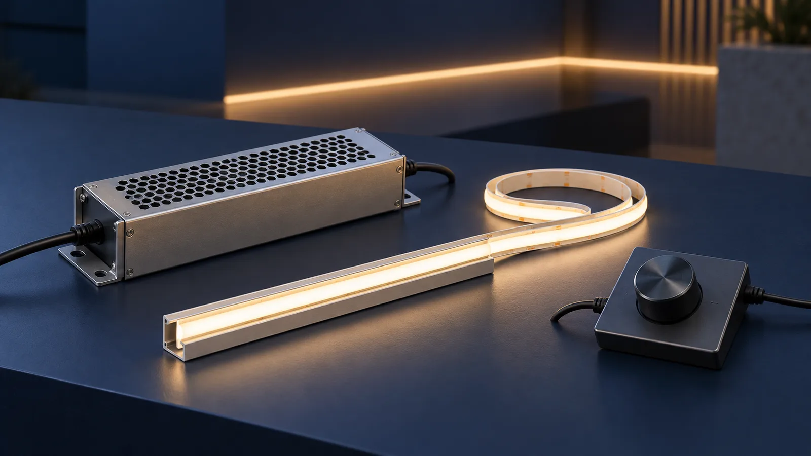
Usually, no. A normal brightness setting is not a reliable basis for downsizing an LED strip power supply. For a conventional constant-voltage installation, size the supply for the maximum load the system can actually reach, with the manufacturer’s temperature derating and installation requirements applied. A smaller supply needs a documented, validated limit on that reachable load, not simply an instruction to keep the dimmer low.
Dimming can reduce average energy consumption. Equipment capacity is a different question: the installation must also tolerate startup, full-output commands and the operating conditions inside its enclosure. This guide concerns low-voltage constant-voltage strips, not mains-voltage strips or constant-current LED modules.
Start with the installed strip, not the usual brightness
Record the exact voltage variant, power per metre and length on each supply. Add every branch that can operate simultaneously. Do not use reel length as a substitute for connected length, and do not assume two strips with the same LED density draw the same power.
The catalog’s 8mm CRI95 COB model lists 12 W/m and DC12/24V variants. Using the 24V variant for an illustrative 8 m connected load:
| Calculation | Illustrative result |
|---|---|
| Strip load: 8 m × 12 W/m | 96 W |
| Nominal strip current: 96 W ÷ 24 V | 4 A |
| Routine operation at a lower dimmer setting | Does not remove the reachable 96 W state |
These are planning figures based on catalog power, not measured consumption or an approved wiring design. Confirm the selected model’s actual requirements, controller consumption and supply compatibility. The calculation alone does not establish an acceptable branch length or cable size. Use the power and voltage-drop guide for that separate check.
A supply marked 100 W is not automatically adequate for this example. Check its available output at the actual ambient temperature, ventilation and mounting position. Do not replace the manufacturer’s derating curve with a universal percentage rule.
Check what happens when the user is not controlling it
Before accepting a reduced-load design, ask the installer or controls supplier to establish the following states safely:
- First power-up and power restoration after an outage.
- A factory reset, controller replacement or lost configuration.
- Local wall control, remote control and app commands at maximum output.
- Scene recall, scheduled operation and any maintenance override.
- Loss of the dimming signal, according to the supply or controller documentation.
Record the documented behavior and verify normal, accessible states on a correctly rated sample installation. Do not deliberately overload a smaller supply to find its limit, bypass protection or alter live wiring. Mains work and design approval belong to a qualified installer.
If any ordinary command can restore full output, the design still has a full-output load. A label saying “maximum 50%” or a staff instruction does not prevent that command.
A dimmer percentage is not an electrical guarantee
PWM dimming switches the load rather than necessarily lowering the voltage applied during each on-period. The MEAN WELL PWM-40 datasheet, for example, describes a constant-voltage PWM output whose duty cycle changes with dimming. That is an example of one supply family, not proof of compatibility with an unspecified controller or strip.
Lower average power does not, by itself, establish acceptable peak loading, transient response or thermal behavior. Conversely, the pulse load alone should not be used to invent a sizing rule for every dimming system. The supply and controls manufacturers must confirm the combination’s operating envelope.
| Proposed basis for a smaller supply | Purchasing decision |
|---|---|
| Customers usually select low brightness | Retain capacity for the reachable maximum |
| An app slider has a software maximum | Confirm whether reset, replacement or another control can defeat it |
| A documented engineered limit prevents excessive load | Ask the designer and equipment manufacturers to validate the complete system |
| The supplier says its overload protection will handle it | Protection is not approval for routine overload operation |
A validated engineered limit may justify a different capacity calculation. It needs to cover permitted operating states, failure behavior and the selected hardware. This article cannot approve that exception remotely.
Put the maximum state in the order specification
Send the strip model, voltage, connected metres per supply, branch layout and control method with the enquiry. Ask for the supply’s available output at the intended temperature and its response to a missing control signal. Include the enclosure and access requirements; a supply selected on an open bench may face different conditions in a cabinet.
Keep a record of the full-output load calculation, derating reference, controller ratings and agreed maximum state. If the project depends on a limit, identify who validates it and how a replacement controller preserves it. Use the quote form to share these requirements before comparing equipment prices.
Keep the electricity estimate with the operating schedule, so it is not mistaken for the supply’s required capacity.
Catalog & Sourcing Note
This article is prepared from our current product catalog and B2B specification workflow. Electrical, waterproofing and installation requirements vary by model and market, so confirm the final specification and approved sample before ordering.
Discuss Your Specification