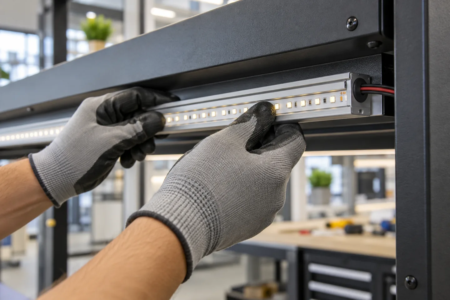
Yes, after checking the surface and electrical detail
Low-voltage LED strip can be installed on steel, aluminum and many painted metal fixtures. A clean aluminum profile is usually the most controlled mounting detail because it supports the strip, protects the PCB edges and provides a defined surface for the adhesive.
Direct mounting can work on smooth metal, but it needs more than peeling the liner and pressing the strip down. Check whether the surface is oily, oxidized, painted, powder coated, textured or curved. Keep copper pads and damaged PCB edges away from conductive metal. Protect cables where they pass through holes or sharp sheet-metal edges.
For any enclosure that contains mains wiring or an AC/DC power supply, a qualified electrician should confirm grounding, bonding, cable entry and local installation requirements. The adhesive backing on LED tape is not electrical protection for a metal enclosure.
Metal helps with heat and exposes installation mistakes
An intact flexible PCB has an insulating base, and many strips also carry adhesive tape on the back. Problems arise when the PCB is cut roughly, a solder pad overhangs an edge, a screw pierces the strip or a cable rubs against a burr. Conductive metal can turn that small defect into a short circuit.
Metal can also move heat away from the strip, especially when a flat PCB sits inside a suitable aluminum channel. The actual result depends on contact area, strip power, profile mass, airflow and ambient temperature. A thin decorative trim is not automatically an adequate heat sink. Measure the production-intent assembly after warm-up rather than assigning a temperature benefit from material name alone.
The metal finish affects adhesion. Mill-finish aluminum, powder-coated steel, oily galvanized sheet and painted retail shelving can all produce different results with the same tape.
Prepare and test the exact finish
Use the adhesive manufacturer’s instructions for the tape supplied on the proposed strip. Test the production finish with these steps:
- Identify the metal and finish, including paint or powder-coat system where known.
- Remove grease, dust, release agents and metalworking residue with a cleaner compatible with that finish.
- Let the surface dry fully.
- Apply the strip at the temperature range specified for the adhesive.
- Press evenly along the complete bond line without pressing directly on LEDs or components.
- Allow the bond to develop before loading, heating or moving the assembly.
- Test a hidden area for staining, coating lift and adhesive compatibility.
3M’s surface-preparation guidance for VHB tape recommends clean substrates and explains that heavy oil, oxidation, paint and other surfaces may need different preparation. Those instructions apply to the named 3M tape systems. They illustrate why a buyer must identify the actual backing tape instead of treating all double-sided adhesives as interchangeable.
Do not use an aggressive solvent without checking the coating and the strip materials. It may soften paint, cloud a diffuser or attack the strip jacket.
Inspect the electrical path before bonding
PCB edges and cut points
Make clean, square cuts only at the marked points. Check that no copper pad or solder bead can contact the metal. Add the insulation, connector housing or end treatment specified for the model. Do not depend on a thin adhesive layer to cover a protruding wire strand.
Cable holes
Deburr drilled or punched holes. Use a suitable grommet, gland or bushing, and add strain relief so cable movement does not pull on the strip pads. Confirm that the cable jacket is suitable for the environment.
Screws and clips
Place mechanical fasteners beside the strip or through a purpose-made profile. A screw through the flexible PCB can cut tracks, expose copper and create a hot connection.
Driver and metal enclosure
Keep the AC side segregated from low-voltage strip wiring according to the equipment instructions and local design. Confirm the protective-earth arrangement for exposed conductive parts. Do not place an open-frame supply where a user can touch terminals or where metal swarf can enter it.
Waterproof strip
A silicone jacket does not remove the need to protect field cuts, cable entries and connectors. A cut end resting against wet metal can fail even when the untouched strip construction has an IP rating. Review the full joint using the waterproof connection guide.
Choose adhesive, clips or a profile by the job
| Mounting method | Suitable starting point | Main check |
|---|---|---|
| Strip backing adhesive on smooth metal | Clean, horizontal, low-disturbance detail | Actual tape, finish compatibility and service temperature |
| Aluminum profile with clips or screws | Retail fixtures, cabinets, signs and permanent linear details | Internal width, diffuser clearance and cable route |
| Mechanical strip clips | Curved or exposed runs where adhesive is unreliable | Clip spacing, PCB protection and expansion |
| Bonded profile | Metal surface that should not be drilled | Structural adhesive selection and removal plan |
| Magnetic carrier designed for the assembly | Frequently repositioned temporary fixture | Holding force, cable pull and vibration |
Vertical and overhead installations deserve a secondary retention review. Heat, cable weight, cleaning and vibration can peel a bond over time. A profile may also make replacement easier because the complete lighting element can be removed without scraping tape from a finished fixture.
Build the sample on production metal
A strip stuck to a clean aluminum ruler is not representative of a powder-coated display cabinet. Ask for an offcut of the actual fixture or a coupon with the same finish.
Record:
- metal and coating identification;
- cleaning method and application temperature;
- strip, backing tape and profile models;
- pressure and dwell time before testing;
- orientation, cable pull and bend at the entry point;
- operating power and warm-up period;
- surface and nearby component temperatures measured by an agreed method;
- condition after repeated on/off cycles and planned cleaning exposure;
- removal method and any coating damage.
Inspect for lifted corners, bubbles, adhesive creep, discoloration, cable movement and contact between copper and metal. If the project uses several colors or finishes, test each one. Different powder coats can bond differently even when the metal underneath is the same.
What the buyer should specify
Send the supplier and fabricator:
- metal type, finish and surface texture;
- horizontal, vertical, overhead or curved orientation;
- strip voltage, power per meter, PCB width and construction;
- aluminum profile section and diffuser, if used;
- backing tape identity and application instructions;
- mounting clips, fastener spacing or secondary retention;
- cable exit, grommet, gland and strain-relief detail;
- ambient temperature, moisture, cleaning agents and vibration;
- driver location and enclosure arrangement;
- sample test and visual acceptance rules;
- service and replacement access;
- destination and buyer-specified electrical requirements.
Use the aluminum profile selection guide before finalizing the section. For a model comparison, send the fixture drawing and metal finish through the quote form; the response should identify the exact strip construction rather than assume that one backing tape suits every surface.
Catalog & Sourcing Note
This article is prepared from our current product catalog and B2B specification workflow. Electrical, waterproofing and installation requirements vary by model and market, so confirm the final specification and approved sample before ordering.
Discuss Your Specification