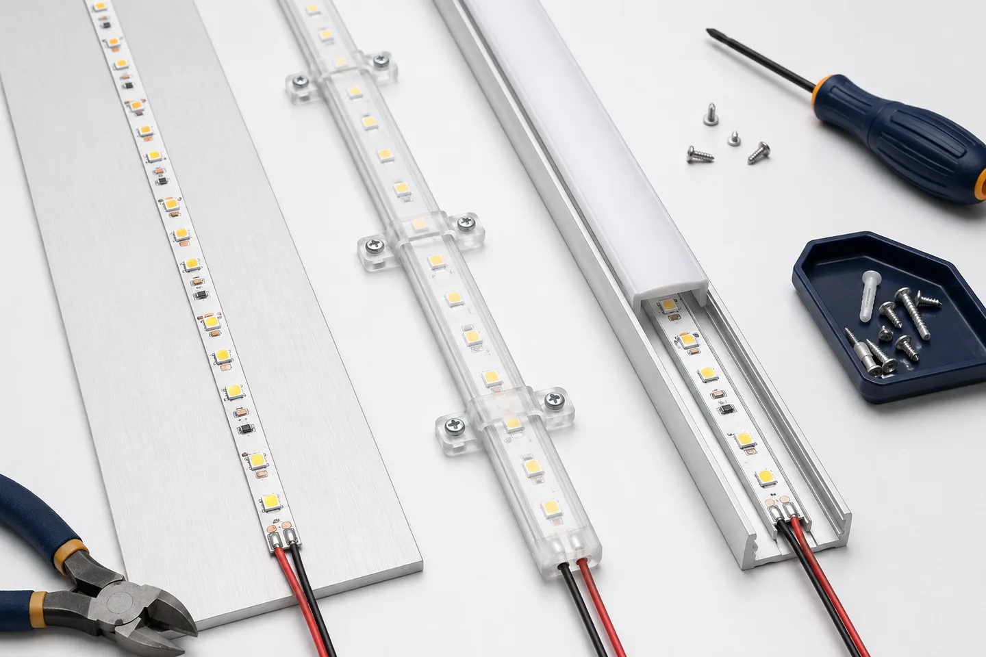
Quick recommendation
Use adhesive tape for a clean, smooth, dry surface when the strip is light, accessible and unlikely to be disturbed. Use mounting clips for encapsulated or heavier strips, removable displays and locations where the tape bond needs mechanical backup. Use an aluminum channel when appearance, straightness, heat spreading, protection or future replacement matters.
These methods are not mutually exclusive. A common commercial detail places adhesive-backed strip inside a screwed aluminum profile. Clips may also secure the ends of an encapsulated run. The right choice depends on the exact strip cross-section and substrate, not only on whether the product arrives with tape.
Mounting-method comparison
| Decision factor | Adhesive tape | Mounting clips | Aluminum channel |
|---|---|---|---|
| Fast installation | Strong | Moderate | Moderate |
| Smooth appearance | Good when installed straight | Clip spacing may remain visible | Best control of straightness and diffuser |
| Removal and service | Difficult without disturbing tape | Good | Good when access is planned |
| Textured/porous surface | Weak without a prepared carrier | Often better with suitable anchors | Good with suitable fasteners |
| Encapsulated strip | Bond must match silicone/jacket | Often preferred | Only when internal dimensions fit |
| Overhead or vertical security | Needs risk review and possible backup | Good mechanical support | Good when profile is fixed securely |
| Heat spreading | Depends on substrate | Depends on substrate | Can help when strip-to-profile contact is sound |
| Curved route | Possible within bend limits | Good with close, correct spacing | Needs a bendable/suitable profile or segmented layout |
No table can approve the final installation. Verify the substrate, fastener, environmental conditions and strip dimensions on a mock-up.
Choose by mounting surface
Painted drywall or plaster
Adhesive can lift paint rather than fail at the tape interface. A removable display should use a mechanically fixed carrier, profile or purpose-designed temporary mounting system. Check for hidden services before drilling.
Powder-coated or anodized metal
A clean, flat metal surface is often suitable for tape and can spread heat. Confirm that the coating is stable and compatible with the selected adhesive. An aluminum profile improves alignment where multiple sections must meet.
Raw wood or MDF
Porosity, dust and changing moisture make direct tape bonds less predictable. Seal and prepare the surface according to the adhesive instructions, or fix a profile mechanically.
Glass and smooth tile
Tape can form a strong bond after correct cleaning, but removal may be difficult and the strip remains visible. A slim profile creates a straighter line and can conceal the tape edge and wiring transition.
Masonry, concrete or textured ceilings
Do not treat the supplied tape as an anchor. Use a mechanically fixed profile or clips with fasteners selected for the substrate and load. The installer must check local construction and electrical requirements.
Shelves, joinery and retail fixtures
A recessed or surface-mounted profile usually gives the most repeatable finish. Plan driver access, cable exit, diffuser removal and replacement length before the cabinet is closed.
How to select LED strip mounting clips
Measure the finished width and height, including silicone coating or sleeve. A clip intended for bare 8mm tape will not safely retain a thicker waterproof strip. Request a section drawing or physical sample when the fit is important.
Check five details:
- Internal clip dimensions: enough clearance to hold without crushing.
- Emitter clearance: the clip must not block an LED, component or cut pad.
- Fastener and substrate: screw type, anchor and corrosion resistance must suit the base material and environment.
- Spacing: closer support is usually needed near ends, connectors, bends and downward-facing runs; define spacing from a tested installation rather than a universal number.
- Bend direction: clips cannot make a strip bend across an axis it was not designed to follow.
Do not drive a screw through the flexible PCB. Do not tighten a clip until it deforms the jacket. At cable entries, add strain relief so movement is not transferred into the first solder joint.
Signify’s WiZ strip installation manual shows both surface cleaning and supplied screw-mounted clips for that particular product. It is a useful example, not a spacing rule for every strip.
How to install an adhesive-backed strip
- Confirm that the surface is sound, smooth, dry and compatible.
- Remove dust, grease and cleaner residue with the method specified for the tape and substrate.
- Dry-fit the full route, including cable exits and cut locations.
- Peel the liner in short sections without touching the adhesive.
- Keep the strip straight and apply uniform pressure along the bond line.
- Respect the tape maker’s time and temperature conditions before loading or operating the strip.
Do not stretch the PCB to correct alignment. Do not bridge gaps, joints or screw heads with unsupported tape. Heat, contamination and peel force at cable ends are common reasons for a bond to lift.
3M’s VHB application guidance emphasizes surface preparation and final application pressure. Follow the instructions for the actual adhesive supplied; the presence of a release liner does not identify its chemistry or performance.
When aluminum channel is worth it
Choose a profile when the buyer needs a straight architectural line, physical protection, a diffuser, replaceable modules or a defined mounting surface. Confirm:
- internal width is greater than the finished PCB width, including solder joints;
- profile depth and diffuser control visible points at the viewing distance;
- the strip can make continuous contact with the channel base;
- end caps and cable exits do not pinch conductors;
- mounting screws or clips remain accessible;
- the diffuser can be removed after nearby finishes are complete.
A channel does not fix an undersized power system or guarantee a dot-free line. Build a mock-up with the exact strip density, profile, diffuser, surface color and viewing angle. The COB and SMD comparison explains why source layout changes the visual result.
Installation acceptance check
Before handover, inspect the whole run with the lights off and on:
- no clip covers an emitter or crushes a silicone jacket;
- no screw touches the PCB or conductor;
- strip and profile are straight at normal viewing distance;
- no section lifts after the agreed bond-conditioning period;
- cables have strain relief and service slack;
- diffusers and end caps remain secure without pinching wire;
- the run operates without visible dark joints or unexpected color change;
- drivers, controllers and connectors remain reachable;
- removal of one service section has been demonstrated where maintenance matters.
For purchasing, send the supplier a cross-section showing the strip, profile or clip, diffuser and mounting surface. That small drawing prevents more mistakes than an instruction such as “include mounting clips,” because it defines what must physically fit together.
Catalog & Sourcing Note
This article is prepared from our current product catalog and B2B specification workflow. Electrical, waterproofing and installation requirements vary by model and market, so confirm the final specification and approved sample before ordering.
Discuss Your Specification