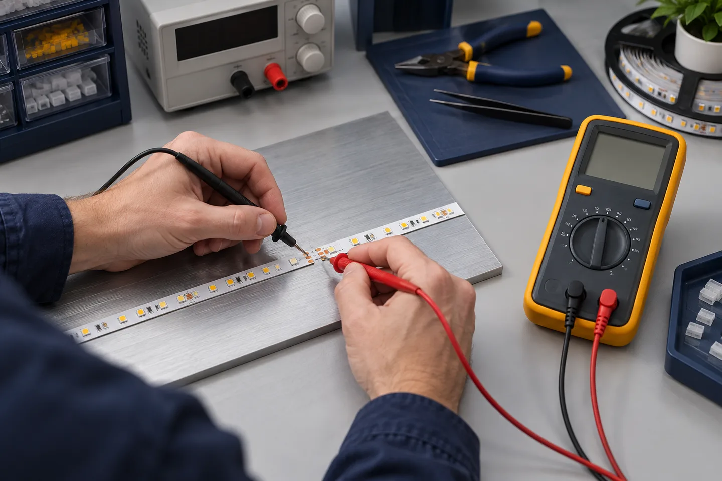
Start with the safety boundary
For a 12V or 24V constant-voltage LED strip, a multimeter can check the power-supply output, polarity, voltage at different points and continuity of isolated conductors. It cannot prove lumen output, color quality, thermal life or full production consistency.
This guide covers the low-voltage DC side only. Do not probe a live mains input or a mains-voltage LED strip unless you are trained, authorized and using a meter, leads and work method suitable for that circuit. Isolate power before changing connections or selecting resistance, continuity or diode mode.
Read the multimeter manual first. Confirm that the leads are sound and that the red lead is in the V/ohm input, not the current input. Fluke’s DC voltage measurement guide shows the usual COM and voltage-jack setup and explains polarity display.
What a multimeter can and cannot tell you
| Test | Circuit state | Useful for | Important limit |
|---|---|---|---|
| DC voltage | Powered | Supply output, polarity and voltage drop | Does not measure light output |
| Continuity | Power isolated | Open copper path, broken wire or connector | Semiconductor paths can confuse the result |
| Resistance | Power isolated | Comparing a simple wire or contact | A complete strip is not a simple resistor |
| Diode mode | Power isolated | Limited component-level checks | Test voltage may not forward-bias a full LED segment |
| Current | Powered with meter in series | Branch-current investigation | Wrong setup can short the source or blow the meter fuse |
For most site diagnostics, start with voltage. Current measurement is not the first step. A clamp or inline measurement method may be safer for the specific system, but the instrument and conductor arrangement determine what is possible.
Never place a meter set to amps directly across the power-supply output. That connection can short the source and damage the meter, its fuse or the circuit.
Test the low-voltage supply output
1. Identify the system before touching the probes
Read the strip and power-supply labels. Record rated output voltage, polarity, controller type and strip model. Do not infer voltage from the connector shape or LED package.
Disconnect the strip while power is off. Inspect for crushed cable, loose terminals, overheated connectors, moisture and reversed wiring. If the supply or wiring is visibly damaged, stop the test.
2. Set the meter for DC voltage
Place the black lead in COM and the red lead in the V/ohm jack. Select DC volts. On a manual-ranging meter, choose a range above the expected output.
Restore power without exposing or touching the mains side. Place the black probe on the negative output and the red probe on the positive output. A negative sign normally indicates reversed probe polarity; it does not make an unknown connection safe.
Record the output with no strip connected. Compare it with the power-supply data, not with a universal tolerance copied from another model.
3. Compare no-load and loaded readings
Switch off, reconnect the intended strip load, then power the system again. Measure the voltage at the supply output. A supply that reads normally with no load but drops sharply after connection may be overloaded, entering protection, connected through a bad terminal or faulty.
Do not conclude that the driver is defective until the branch load, wiring and possible short circuit have been checked.
Test voltage along the operating strip
With the correct strip operating, measure across positive and negative pads at three locations:
- the strip feed;
- the middle of the longest branch;
- the far end.
Use accessible test pads. Keep probe tips from bridging adjacent pads. Small insulated probe accessories are safer than pressing long exposed metal tips into a dense PCB.
Calculate the change:
voltage drop (V) = feed voltage - far-end voltage
voltage drop (%) = voltage drop ÷ feed voltage × 100
For example, a hypothetical branch measured at 24.1V at the feed and 21.9V at the far end has a 2.2V drop, or about 9.1%. That calculation does not decide whether the result is acceptable. The visual target, strip design, controller behavior and project limit must be agreed first.
If the voltage falls gradually along the strip, review branch length, PCB loss and feed strategy. A sudden step across one connector points more directly to contact resistance or a poor joint. The wire-gauge guide helps separate cable loss from loss along the flexible PCB.
Use continuity and diode mode only with power isolated
Switch off and disconnect every power source. Check for stored energy and follow the meter maker’s instructions before selecting continuity or resistance.
Continuity mode is useful for a cable, fuse, connector contact or copper path that should be electrically continuous. Test each conductor separately. A beep only means resistance is below the meter’s continuity threshold; it does not prove the joint will carry the required current without heating or voltage loss.
Testing across the positive and negative rails of a complete strip is less useful. LEDs, resistors, control ICs and capacitors create paths that may charge, conduct in one direction or show a changing reading. Compare like-for-like sections only when you understand the circuit.
Diode mode may faintly illuminate one individual LED on some bare boards. It may do nothing on a segment containing several series LEDs, a controller IC or protective components. Do not declare the segment failed from that result alone.
Interpret the pattern, not one number
| Symptom | First measurements | Likely area to investigate |
|---|---|---|
| Entire strip is off | Supply output, feed-pad voltage and polarity | Supply, controller, input connection or reversed feed |
| First part works, rest is off | Voltage before and after the first dark section | Cut-point joint, cracked PCB or failed component |
| Far end is dimmer | Feed, middle and far-end voltage under load | Run length, PCB loss, cable or feed layout |
| Light flickers when cable moves | Voltage across connector while gently checking the joint | Loose contact, strained solder joint or damaged lead |
| One branch fails but others work | Voltage at distribution output and branch feed | Branch fuse, terminal, cable or local connector |
| Supply cycles on and off | Loaded output voltage and calculated load | Short circuit, overload, thermal protection or faulty load |
Never bypass a protection device simply to make the strip illuminate. If an overcurrent or thermal device operates, find the cause.
What a buyer should record from a sample test
A phone photo of a meter display is not enough. Record:
- strip model, rated voltage, watts per meter and tested length;
- power-supply model and selected output setting;
- controller, dimmer and connector arrangement;
- ambient condition and whether the strip was in a profile;
- meter model, lead setup and measurement points;
- no-load voltage, loaded supply voltage, feed voltage and far-end voltage;
- operating time before the readings;
- observed brightness, color or intermittent behavior;
- photos that show the probe location as well as the display.
Use the same method on the production-intent sample and shipment checks. Comparable records help distinguish a product change from a wiring or installation problem.
Catalog & Sourcing Note
This article is prepared from our current product catalog and B2B specification workflow. Electrical, waterproofing and installation requirements vary by model and market, so confirm the final specification and approved sample before ordering.
Discuss Your Specification