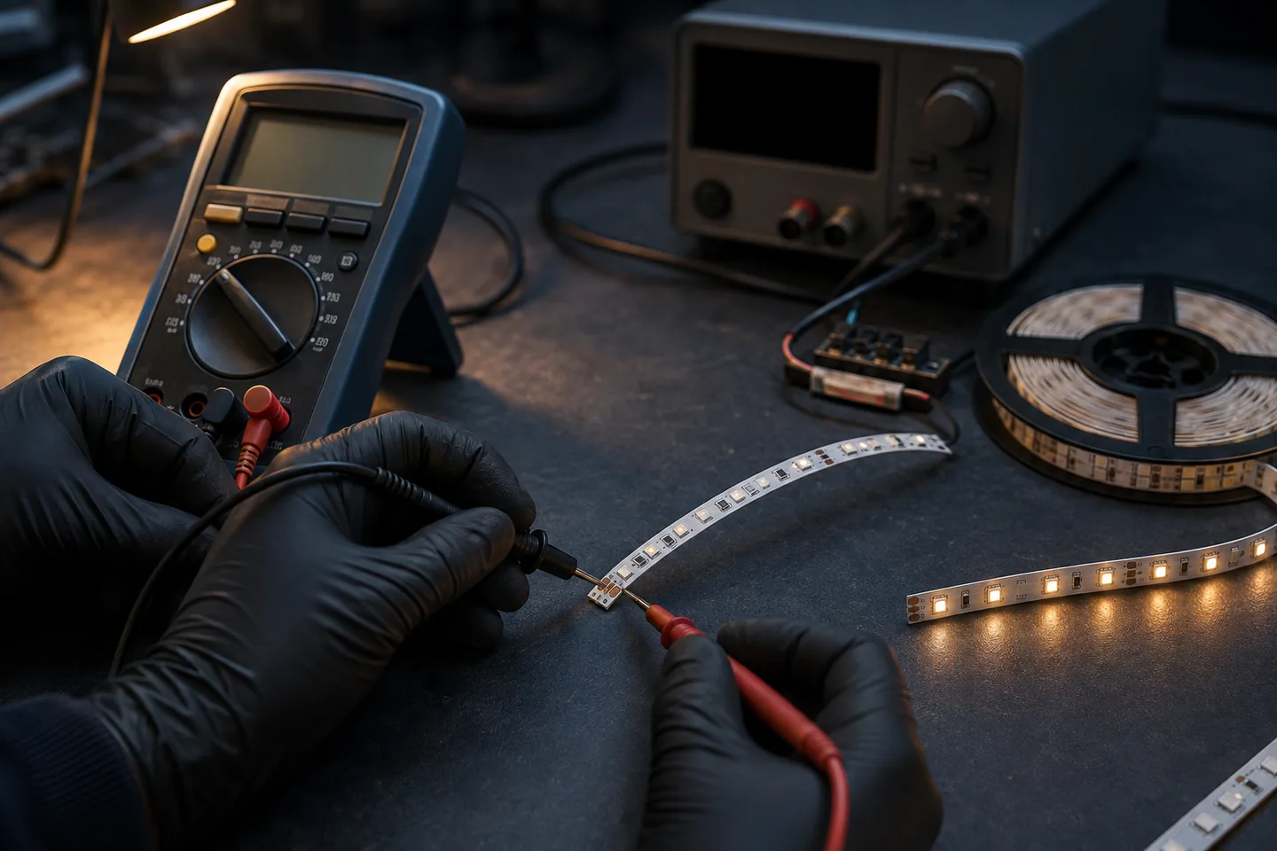
Start here: isolate the failed section
If LED strip lights are not working, do not start by buying a new strip. First decide whether the fault is upstream of the strip, at one connection, or inside one cut section. Disconnect mains power before opening a driver enclosure or touching terminals. If you are not qualified to work on mains wiring, stop at the plug-in or low-voltage side and use an electrician.
Record the symptom before moving anything:
- no light anywhere;
- the first section works but the rest is dark;
- one color or white channel is missing;
- brightness changes when a cable is moved;
- the strip works briefly, then stops;
- the fault begins after a connector, cut point or injection point.
Also photograph the driver label, controller connections, strip markings and branch layout. Those details prevent a troubleshooting step from creating a second fault.
Use substitution carefully
A known-good component can isolate a fault, but only if its voltage, polarity, control type and load capacity match. Do not test a 12V strip with a 24V supply. Do not connect an addressable strip to an analog RGB output because the plugs appear similar.
When no part of the LED strip turns on
Work from the source toward the load.
1. Check the supply path
Confirm the outlet or upstream circuit using an appropriate safe method. Inspect the switch, plug, fuse and visible cable for damage. If the driver has a removable low-voltage connector, make sure it is fully seated.
Do not infer that a driver is healthy from an indicator lamp. Measure its low-voltage output with the load disconnected and connected, following the equipment instructions. A supply can show nominal voltage without load and collapse when the strip is connected.
2. Check voltage and polarity at the strip input
At the first strip pads or input connector, verify the expected DC voltage and polarity. If voltage is correct at the driver but absent at the strip, the open circuit is in the controller, cable, connector, fuse or terminal between them.
If voltage drops sharply only when connected, disconnect the load and check for reversed polarity, a short, an overloaded driver or a damaged controller. Do not repeatedly reset protection without finding the cause.
3. Bypass only when the topology permits it
A qualified technician can sometimes test a single-color constant-voltage strip directly from a current-limited matching supply, temporarily excluding the controller. That method does not apply unchanged to CCT, RGB or addressable strips. Use the exact wiring data.
Why only half of an LED strip works
When everything before one point lights normally and everything after it is dark, inspect the boundary. Common causes include:
- a cut made outside the marked cut point;
- copper pads not seated beneath connector contacts;
- a cracked solder joint or torn flexible PCB;
- reversed section orientation on an addressable strip;
- an open copper track caused by bending at the cut point;
- a failed LED/component section interrupting a series path;
- no power injection or excessive voltage drop on a long run.
With power isolated, inspect the first dark cut section under magnification. Check that the connector matches PCB width and conductor count. The strip should enter squarely, with clean copper beneath each contact.
For a direct clip connection, Signify’s CorePro/Master LED strip design guide shows an important model-specific principle: the strip’s soldering point must sit under the connector springs, and connector load limits still apply. Use that as a reason to verify contact placement—not as a universal rating for unrelated connectors.
Distinguish an open circuit from voltage drop
An abrupt transition from normal light to complete darkness usually suggests an open connection or failed section. A gradual reduction in brightness or color shift toward the end more often points to voltage drop. Measure voltage at the start, before the fault and after the fault under controlled load.
Use the voltage-drop calculation guide before adding another feed. Power injection must preserve correct polarity and share a design-approved supply arrangement.
When one color is missing or colors are wrong
For analog RGB, RGBW or CCT tape, test one channel at a time. If one channel fails along the whole run, inspect controller output and the corresponding conductor. If it fails only after one connector, the contact or track at that boundary is the likely starting point.
Wrong colors usually mean channel order is crossed, not that the LEDs changed color. Compare the controller terminal labels with the strip pads. Do not trust red, green or blue wire insulation unless the approved assembly drawing assigns it.
Addressable strips add other possibilities: wrong data direction, incompatible IC protocol, missing signal reference, incorrect pixel settings or corrupted data beyond a damaged pixel group. The addressable versus RGB explanation helps identify which diagnostic path applies.
When the strip works only sometimes
Do not wiggle live connections with bare hands. Isolate power, then inspect and mechanically test suspect joints.
| Symptom | Likely areas to check |
|---|---|
| Changes when connector is touched | Poor pad alignment, weak spring contact, cable strain or cracked solder joint |
| Stops after warming up | Driver or controller overload, thermal protection, high-resistance joint or inadequate heat path |
| Flickers at low brightness only | Controller/driver dimming behavior, minimum load or control signal |
| Random reset on addressable effects | Supply dip, data integrity, reference/ground or controller capacity |
| Works after power cycling | Controller state, driver protection or intermittent short |
Measure temperatures only with a documented method and compare them with component limits. A warm component is not automatically faulty, and a cool enclosure does not prove the internal junction is safe. For repeated flashing, follow the dedicated LED strip flicker diagnostic.
Repair one section or replace the run?
A local repair can be reasonable when the failure is clearly isolated, the remaining strip is healthy, a valid cut point exists on both sides and the new joint can be supported and protected for the environment.
Replace more of the run when:
- heat, moisture or overvoltage affected several sections;
- copper tracks are brittle, discolored or lifting;
- repeated faults appear at different points;
- the exact replacement section has incompatible voltage, color, PCB width or cut interval;
- a repaired joint cannot fit safely in the profile or enclosure;
- matching brightness or color across visible sections is critical.
Never repair a fault until the cause is removed. A new strip connected to an overvoltage supply, overloaded controller or wet joint may fail again.
For soldered repairs, use the LED strip soldering procedure. Cutting and reconnecting also changes the protection of an encapsulated product; follow the waterproof connection guide where moisture is involved.
Prevent repeat faults in procurement and installation
For samples and production orders, record:
- exact strip and driver models;
- voltage, watts per meter and maximum branch length;
- controller topology and channel/data pinout;
- cut interval, PCB width and connector part number;
- feed cable size, route length and injection points;
- joint, strain-relief and environmental sealing method;
- operating enclosure and ventilation;
- approved sample photographs and wiring diagram;
- incoming inspection for polarity, connectors and visual damage;
- loaded burn-in or functional test agreed for the application;
- fault-report format with lot, reel and installation location.
Long-run behavior depends on the model and feed design. For example, the catalog includes an 8mm SMD2835 120 LED/m 20m no-drop configuration, but that listing is not permission to extend every strip to 20m. Confirm the exact ordered model and complete circuit.
When requesting help, send the symptom, where it begins, measured voltages, branch length, driver/controller labels and clear connection photos through the contact page. That evidence is far more useful than “the strip is broken.”
Catalog & Sourcing Note
This article is prepared from our current product catalog and B2B specification workflow. Electrical, waterproofing and installation requirements vary by model and market, so confirm the final specification and approved sample before ordering.
Discuss Your Specification