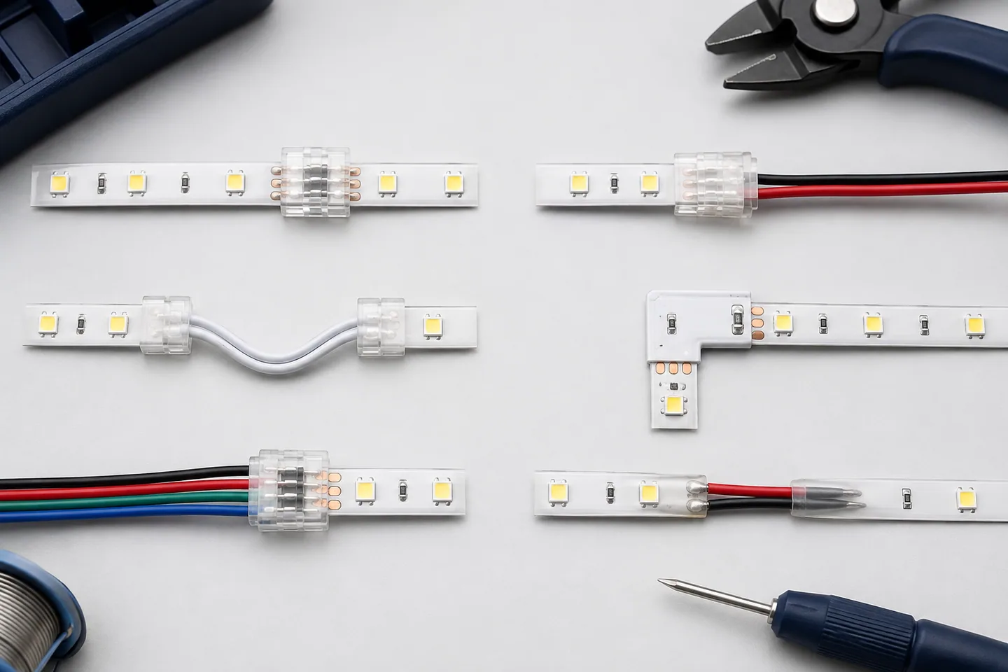
The best connector is the one qualified for the exact strip
There is no universal best LED strip connector. For a dry, accessible cabinet, a matching solderless clip may be the quickest serviceable choice. For a high-current branch, narrow profile, repeated movement or exposed location, a properly engineered soldered or factory-terminated joint may be more reliable.
This guide compares six useful connection types by installation fit. Match the connector to the strip construction, pad geometry, current, environment and service plan rather than ordering from appearance alone. The connection methods were reviewed on September 6, 2026.
Six useful LED strip connector types
1. Straight strip-to-strip clip
Best for: joining two compatible cut sections in a straight, accessible indoor run.
The clip brings the copper pads of two strips under spring contacts. It saves space compared with a wire loop, but alignment is critical. Both strips must have the same PCB width, pad pitch, conductor count and pad order.
Avoid it where the joint must bend, carry cable pull, disappear inside a profile it cannot fit, or handle more current than the connector allows.
2. Strip-to-wire connector
Best for: connecting a strip to a driver/controller lead or crossing a gap.
This design grips the strip at one end and terminates flexible conductors at the other. It can make cabinet modules easier to replace. Specify wire size and length, because a connector supplied with thin leads can become the limiting part of an otherwise adequate circuit.
3. Flexible corner jumper
Best for: going around a corner without sharply folding the PCB.
Two strip clips linked by flexible wire allow the lighting faces to remain oriented correctly. Leave room for the jumper and strain relief. Do not trap the wire beneath a diffuser or pull the clips sideways.
This is generally more forgiving than forcing the strip into a tight 90-degree fold. Review the corner-bending guide before deciding whether a connector is needed.
4. Rigid L, T or cross connector
Best for: clean geometric layouts on one plane, when dimensions are fixed.
Rigid corner boards can produce a tidy layout, but their PCB width, polarity and pad positions must match the tape. T and cross pieces also divide current; every branch still needs a load and voltage-drop calculation.
Use a flexible jumper when walls are not square, the mounting surface moves or dimensional tolerance is uncertain.
5. Multi-pin RGB, RGBW or CCT clip
Best for: serviceable analog multi-channel connections with a verified common-pole and channel order.
The pin count is only the first check. A four-pin plug does not prove the same + / R / G / B sequence. Tunable-white and RGB products can also use similar-looking housings for different electrical functions.
Test each channel individually, then test the maximum simultaneous load. For addressable tape, match power, ground, data protocol and direction; a generic “RGB connector” description is insufficient.
6. Soldered wire joint with insulation and strain relief
Best for: compact custom leads, higher reliability under a qualified process, or strips for which a matching clip is unavailable.
Soldering is not automatically better. Excess heat can lift pads, a cold joint can fail intermittently and a heavy cable can tear the flexible PCB. Pre-tin, control heat, inspect for bridges and support the cable. The full LED strip soldering guide covers the process and QC points.
Where moisture or washdown is possible, the finished joint needs an application-specific enclosure or sealing construction. The original strip’s environmental description does not automatically extend across a field-made joint.
Compatibility checks before ordering connectors
PCB width
Measure the actual strip, not only the product-family name. Common widths include 5mm, 8mm, 10mm and 12mm, but construction varies. A loose clip may make intermittent contact; a tight clip can damage the PCB or fail to close.
Pad count, pitch and order
Count the copper pads and measure their spacing. Confirm polarity, common conductor and channel sequence from the exact sample. For addressable tape, also record data input/output direction.
Surface construction
Bare indoor tape, coated tape and silicone-encapsulated tape do not enter the same clip in the same way. Do not scrape or remove encapsulation unless an approved method defines where and how. A connector sold as “waterproof” still needs its complete cable-entry and joint construction evaluated for the installation.
Cut geometry
Some strips leave generous copper on both sides of a cut; others have small or split pads. Cut exactly on the marked line. The cut-and-reconnect guide explains why a connector cannot rescue an invalid cut.
Check load, voltage drop and mechanical reliability
The connector must carry the branch current, not merely fit the strip. Calculate load from the approved strip power and connected length, then compare with the connector’s stated current limit under its installation conditions.
Signify’s official CorePro/Master LED strip design guide gives model-specific connector placement and series-load limits. The useful lesson is that connectors impose their own limits; its numbers must not be copied to other brands or products.
During sample approval, run the longest representative branch at the highest intended simultaneous channel load. Measure voltage before and after the connector and monitor for unstable light, discoloration, odor or abnormal temperature. Use the connector manufacturer’s test conditions and limits rather than inventing a universal temperature threshold.
Mechanically, check:
- pads remain centered under contacts;
- the latch stays closed after cable routing;
- pulling the cable does not load the flexible PCB;
- the joint fits under the diffuser and end cap;
- repeated service does not weaken the latch;
- the connector cannot be reversed during assembly;
- the installed bend radius does not pry the contact open.
Connector selection matrix
| Installation need | First option to evaluate | Main limitation |
|---|---|---|
| Straight, dry, accessible extension | Strip-to-strip clip | Contact alignment and current limit |
| Feed from controller or cross a gap | Strip-to-wire lead | Lead size and strain relief |
| Cabinet or wall corner | Flexible corner jumper | Requires space for cable loop |
| Fixed geometric display | Rigid L/T/cross board | Low tolerance for misalignment |
| Analog color or tunable white | Matching multi-pin clip | Pinout and per-channel rating |
| Compact custom or no matching clip | Qualified soldered joint | Process control and pad damage risk |
| Damp or exposed joint | Purpose-designed sealed assembly | Complete joint must be evaluated, not the strip alone |
For an 8mm SMD2835 strip, “8mm two-pin connector” may be a starting search term, but the sample still has to match pad geometry, selected voltage, coating and current. For a 24V SMD5050 RGB Magic strip, obtain the exact data and power pinout before selecting any clip.
Approve connectors as part of the complete assembly
Ask for a sample using production strip, production connector and production cable. Then record:
- strip model, PCB width and surface construction;
- connector manufacturer and part number;
- conductor count, pitch, polarity and channel order;
- maximum branch current and length;
- wire material, size and length;
- assembly sequence and visual acceptance photos;
- pull/strain-relief method;
- loaded functional test and voltage-drop method;
- joint enclosure or sealing process, where required;
- replacement instructions and spare quantity.
Do not approve a loose connector sent beside a different strip. A useful sample should arrive assembled exactly as production will be supplied and should fit the actual aluminum profile, diffuser and end-cap arrangement.
Send the PCB width, strip model, conductor count, coating, branch current and installation drawing in the quotation form. That lets the supplier confirm a connector-matched sample instead of guessing from a generic plug photo.
Catalog & Sourcing Note
This article is prepared from our current product catalog and B2B specification workflow. Electrical, waterproofing and installation requirements vary by model and market, so confirm the final specification and approved sample before ordering.
Discuss Your Specification