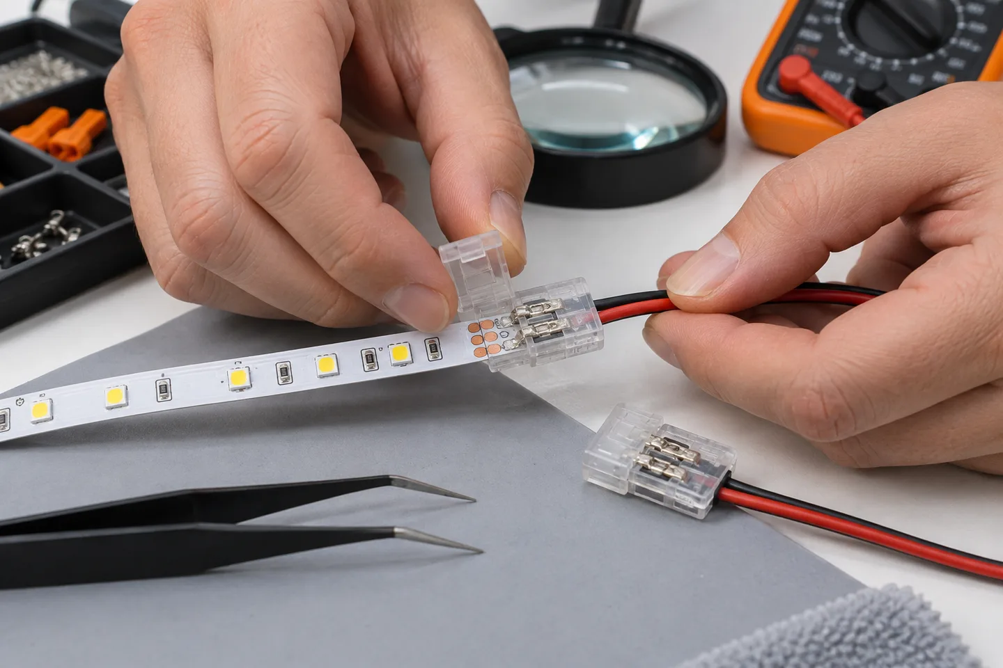
Turn off power, reopen the clip and realign the copper pads
Most LED strip clip-connector faults come from one of five causes: the connector does not match the PCB width or pin count, the strip is not inserted far enough, the contacts miss the copper pads, polarity or color channels are reversed, or cable movement has loosened the joint.
Disconnect the low-voltage supply. Open the latch, inspect the strip at the marked cut point, insert it squarely under the contacts, and close the latch fully. Then support the cable and test a short section before reinstalling the whole run.
If the connector is discolored, melted, cracked or unable to grip the strip, replace it. Extra pressure or tape will not restore a damaged spring contact.
Confirm the connector actually matches the strip
A connector that looks close may still be wrong. Check these details on the sample, drawing or product page:
- PCB width: Measure the bare flexible board, not the widest point of a silicone jacket.
- Pin count: Single-color strips commonly use two conductors; tunable white, RGB and addressable systems use different channel arrangements.
- Pad layout: Contact spacing and pad length must line up with the connector contacts.
- Strip construction: A connector for bare IP20 PCB may not accept a coated or silicone-bodied strip.
- Electrical rating: The connector, wire and branch load must suit the system voltage and current.
- Cable direction: Board-to-wire, board-to-board and corner connectors solve different routing problems.
Do not remove coating until you have confirmed that the connector method calls for exposed pads. Cutting or scraping the wrong area can sever a conductor and can change the moisture-protection detail.
For a multi-channel strip, map each printed pad label from the strip to the controller output. If an RGB strip powers on but shows the wrong color, the fault is often channel order rather than a failed LED. The RGB color troubleshooting guide separates wiring faults from controller settings.
A repeatable seven-step connector repair
1. Isolate the low-voltage circuit
Turn off and unplug the power supply before touching copper pads or connector contacts. Do not work on the mains input. If the installation gives no safe access to the low-voltage side, stop and have a qualified electrician isolate it.
2. Inspect the cut
The cut should follow the strip’s marked line and leave usable copper on the section being connected. A diagonal cut reduces the contact area. If enough strip remains, make a fresh square cut only at the next marked point.
3. Prepare the pads only as required
Clean dry pads make contact more reliably than pads covered by debris or adhesive. For a coated strip, use the preparation method specified for that construction. Do not gouge the copper or leave loose coating inside the clip.
4. Open the latch fully
Partly opening a reusable clip can make the strip hit the contact instead of sliding below it. Check for bent contacts, trapped jacket material and plastic flash.
5. Align and insert
Match positive and negative marks, or each channel mark, before insertion. Push the strip straight until every metal contact sits over its copper pad. The PCB should not be twisted inside the housing.
6. Close and add strain relief
Close the latch evenly. Give the wire a light handling check without yanking the PCB. Secure the lead nearby so movement, door operation or installer handling does not load the connector.
Connector-contact retention depends on contact geometry, housing support and handling. Molex’s engineering overview of connector contact retention is a useful reminder that visual checks and mechanical retention both matter. Use the actual connector supplier’s limits for any pull-test value.
7. Test a short section
Restore power to one short branch. Check all channels, dimming and the area around the connector. A connector that becomes noticeably warmer than an equivalent known-good joint needs investigation, not concealment.
Diagnose the connector by what the strip does
| Symptom | Likely connector-related cause | First check |
|---|---|---|
| Entire section is dark | Open circuit, reversed input or strip not under contacts | Supply voltage, polarity and pad alignment |
| Works when pressed | Low contact pressure or incomplete insertion | Reopen, inspect latch and replace if grip is weak |
| Only one color is missing | One channel misses its pad or channel order is wrong | Compare every strip label with connector and controller |
| Flickers when cable moves | No strain relief, loose conductor or damaged contact | Support cable and replace suspect connector |
| Bright near feed, dim farther away | Voltage drop, not necessarily the first connector | Measure voltage at feed, joints and far end under load |
| Connector is brown or distorted | Heating from resistance, overload or poor contact | Isolate and replace; verify current and wire size |
| Outdoor joint fails after rain | Water entered at pad, cable or cut end | Rebuild with the matched sealed connection method |
For wet locations, a working electrical contact is only half the job. Follow the waterproof connection process for end treatment, compatible sealant and strain relief.
Use a multimeter without creating a second fault
Measure continuity only when power is removed. Fluke’s continuity-testing guidance explicitly starts with de-energizing the circuit. A continuity beep can confirm a conductive path, but it does not prove the connector will carry the required current without excessive voltage drop.
With the circuit operating, a trained person can compare DC voltage immediately before and after a suspect joint, using insulated probes and avoiding adjacent pads. A meaningful drop across one connector under load points to resistance in that joint. Record the load, strip length and measurement points so another technician can reproduce the check.
Never place a meter lead in the current socket and probe across the supply as if measuring voltage. See the full LED strip multimeter guide before measuring a powered circuit.
Know when to replace the connector or change the joint method
Replace the connector when a latch will not stay closed, contacts are bent or pitted, plastic has softened, the cable termination is loose, or the same joint fails again after correct insertion.
A properly made soldered joint can be more compact and may suit high-volume factory preparation, but it needs controlled pad preparation, soldering temperature, insulation and strain relief. It is not automatically waterproof. Use the low-voltage LED strip soldering guide to compare the process with clip connectors.
For installations that need frequent module changes, a correctly matched serviceable connector may still be preferable. The purchasing decision is about repeatability, load, exposure and service method, not whether solder or clips are universally better.
Prevent connector faults before a bulk installation
Add the connection system to the order specification instead of buying it as an afterthought:
- State strip model, PCB width, pin count, pad layout and jacket construction.
- State system voltage, maximum branch current and wire size.
- Request an assembled strip-to-wire sample using production parts.
- Agree on a visual standard for insertion depth, channel order and conductor preparation.
- Define a handling or pull check from the connector maker’s instructions.
- Run the sample at the intended load and inspect voltage drop and joint temperature.
- For wet locations, evaluate the completed sealed sample, including cable entry and cut end.
- Keep one reference assembly for incoming comparison.
When requesting a strip system, send clear photos of the connector and the printed pad labels through the quote form. A width such as “10mm” is not enough to identify pin count, contact pitch or waterproof geometry.
Catalog & Sourcing Note
This article is prepared from our current product catalog and B2B specification workflow. Electrical, waterproofing and installation requirements vary by model and market, so confirm the final specification and approved sample before ordering.
Discuss Your Specification