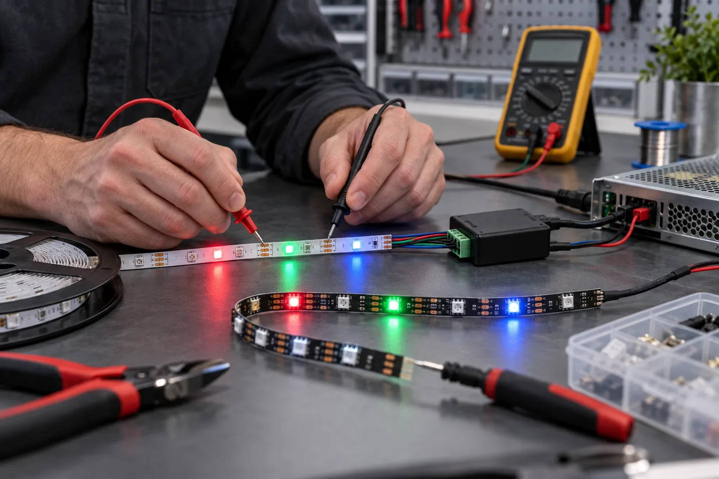
First identify which RGB system you have
An LED strip that will not change color usually has one of four faults: the controller is not receiving the command, the controller does not match the strip, one or more color conductors are connected incorrectly, or the strip is not getting a valid power or data signal.
Do not start by replacing the strip. First decide whether it is analog RGB or addressable RGB. The checks are different.
An analog RGB strip commonly has four copper pads: one shared supply pad and separate R, G and B channels. Every section on that controller output follows the same color command. An addressable strip has power, ground and at least one data connection. Individual pixels or groups can receive different commands, and the data has a defined direction.
The product label, pad markings and controller model are better evidence than wire color. Connector colors can differ between production runs. Adafruit’s analog RGB wiring guide notes that swapped blue and green connections can produce the wrong colors; its digital strip troubleshooting guide also starts with voltage, polarity, wiring and the input end.
This guide covers the low-voltage DC side. Isolate power before moving wires or connectors. Do not open or probe a mains input unless you are trained and equipped for that work.
Run these five checks before deeper testing
- Confirm the rated voltage. Read the strip, controller and power-supply labels. All three must belong to the same system voltage.
- Try a known command. Select solid red, solid green, solid blue and white at full brightness. Record what actually lights.
- Check the controller input. Confirm that the controller receives the expected DC voltage while the strip is connected.
- Inspect both connector ends. Look for an offset plug, a partly inserted terminal, crushed cable, lifted copper pad or solder bridge.
- Remove optional extensions. Test one short, known-good strip section directly at the controller before adding amplifiers, long cables or multiple branches.
If the strip never lights, use the broader LED strip not-working checklist. If it lights but the colors are wrong or fixed, continue below.
Test an analog RGB strip one channel at a time
The strip stays white or one fixed color
Disconnect power and compare every pad label with the controller terminal. A four-pin connector can look fully seated while sitting one position sideways. That can join the shared supply to the wrong pad or leave one channel open.
Restore power and command solid red, green and blue in turn. Simply seeing the strip change is not enough. Each command should operate its matching channel alone. If red produces green and green produces blue, the channel order is wrong. Switch off before correcting it.
If every command produces the same fixed color, bypass the remote as a first diagnostic where the controller provides a local button. Re-pair or replace the remote battery according to that controller’s instructions. A phone application should also be checked for the correct controller, zone and operating mode.
One color never appears
Test a short strip directly on the controller. If the missing color returns, inspect the extension cable, connector and joint for that channel. If it remains missing, move the known command through the controller outputs only when the controller maker’s test method permits it. The goal is to separate a failed controller channel from an open strip conductor.
A multimeter can confirm whether channel voltage changes under red, green and blue commands, but controller topology varies. Do not assume every controller switches the same side of the circuit. Use its wiring diagram.
White looks pink, cyan or yellow
Analog RGB makes white by combining three color channels. A missing or weak channel shifts the result. Compare the color near the feed and at the far end. A color cast that grows with distance often points to voltage loss or unequal conductor resistance. A uniform cast from the first section is more likely to involve channel calibration, wiring or the strip itself.
Test an addressable RGB strip from the input end
Addressable strip adds three failure points that analog strip does not have: signal direction, controller protocol and pixel configuration.
Find the arrows or DI/DO markings on the PCB. The controller signal must enter the data-input end. Power may reach a strip connected backward, so a faint or fixed light does not prove the data direction is correct.
Then confirm:
- controller ground and strip ground are connected;
- the controller is configured for the strip’s actual control IC or protocol;
- pixel count and color order match the strip;
- data cable length and routing follow the controller maker’s limits;
- the test program is a simple, known-good solid-color or chase pattern;
- power is injected without creating an unintended difference between signal-ground references.
If the first pixels work and everything after one point stops, inspect the last working pixel and the first failed section. A failed pixel or damaged data trace can interrupt all downstream data. If random colors appear, return to a short data lead, shared ground, correct input direction and the controller’s default test pattern before changing software effects.
Do not use an addressable controller merely because the plug fits. Our addressable-versus-RGB guide explains what the wiring count alone does and does not prove.
Match the symptom to the next useful check
| What you see | Check next | Common cause to investigate |
|---|---|---|
| Remote changes brightness but not color | Solid-color commands and controller mode | Controller set to a white-only or incorrect output mode |
| Red command produces green | R/G/B pad order from controller to strip | Channel wires crossed |
| One color is absent along the full run | Direct short sample and that channel’s joint | Open conductor or failed controller channel |
| Colors are correct near the feed but wrong farther away | Loaded voltage at feed and far end | Voltage loss or overloaded branch |
| Addressable strip lights but does not animate | Data input end, ground and protocol | Reversed data direction or controller mismatch |
| Pixels after one point stop responding | First failed pixel and PCB trace | Local data-path damage |
| Colors change without commands | Supply stability, data lead and ground | Unstable power, loose connection or signal noise |
| Several branches show the same wrong color | Controller configuration before branch wiring | Shared upstream setting or channel-order error |
Change one variable at a time. Replacing the controller, power supply, extension and strip together may make the system work, but it does not reveal the fault or protect the next installation.
Add a color-function test to sample approval
For a project or wholesale order, test the proposed strip with the actual controller, power supply, connector and longest planned cable. Keep the sample configuration as the production reference.
Record these items:
- strip model, voltage, pad order and control type;
- controller brand, model, output type and selected mode;
- solid red, green, blue and white photographs at the same exposure;
- addressable protocol, color order and pixel count when used;
- feed voltage and far-end voltage under the white command;
- maximum tested branch length and number of branches;
- connector and cable part numbers;
- any difference between the approved sample and the bulk proposal.
A ten-second rainbow video is useful, but it is not a complete acceptance test. Solid colors reveal crossed channels, missing colors and color-order errors much faster.
Catalog & Sourcing Note
This article is prepared from our current product catalog and B2B specification workflow. Electrical, waterproofing and installation requirements vary by model and market, so confirm the final specification and approved sample before ordering.
Discuss Your Specification