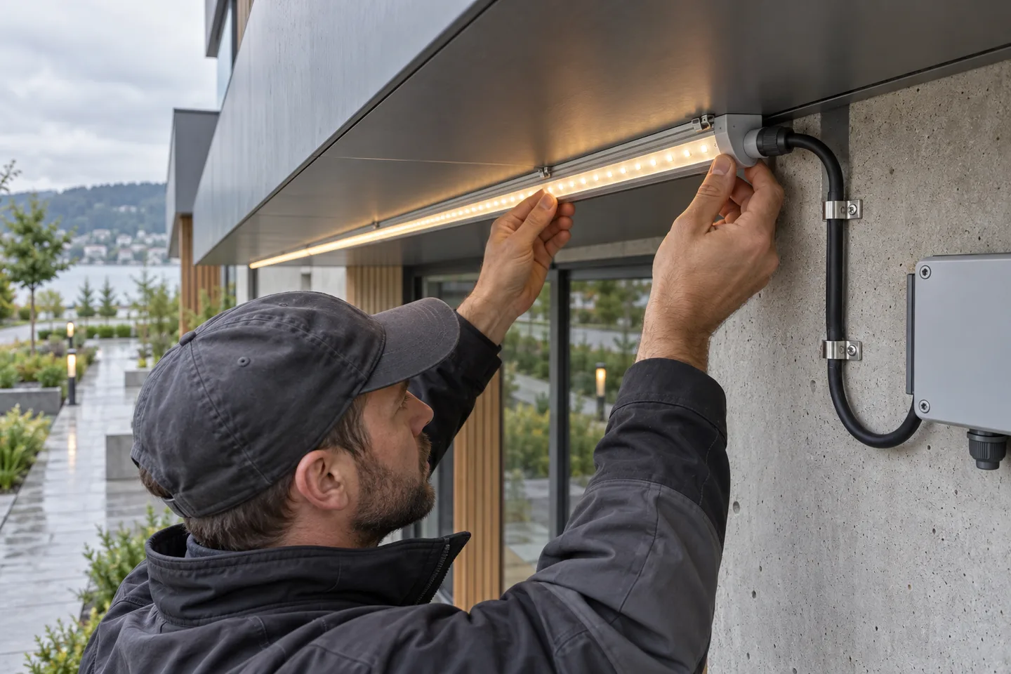
Plan the water path before mounting the first meter
To install LED strip lights outdoors, first divide the site by exposure, select a strip and connection system for each zone, put the power equipment in a suitable accessible location, and provide a mechanical mounting surface. Seal every cut end and cable entry, then test the completed assembly under load.
An ingress rating on an uncut strip does not make the complete installation waterproof. The weak points are usually field-cut ends, connectors, cable glands, low spots that hold water and joints pulled by cable weight.
This guide covers the low-voltage side of the system. A qualified electrician should select, protect and connect mains-voltage equipment according to the rules at the project location.
Map the exposure instead of calling the whole site “outdoor”
Walk the route after rain if possible. Mark where water arrives, where it drains and where maintenance staff will reach the strip.
| Zone | Typical condition | Main design question |
|---|---|---|
| Sheltered | Under a deep canopy with little direct rain | Can condensation or wind-driven rain still reach the joint? |
| Direct weather | Rain and sun reach the strip | Are all cut ends, connectors and cable entries protected as a system? |
| Splash or cleaning | Water may be directed at the fitting | Does the specified assembly and cleaning method match that exposure? |
| Water-collecting detail | Channel, recess or low point can retain water | Can the detail drain, or should the route move? |
Do not treat a water-collecting channel as a normal mounting location. A sealed product can still fail when a field joint sits in water for long periods or when a damaged jacket draws moisture along the conductors.
The IEC page for IEC 60529 describes the IP Code as a classification of protection provided by enclosures. In practical purchasing terms, check what configuration was evaluated and whether cutting, adding a lead or fitting an end cap changes that configuration. Our IP20, IP65 and IP68 comparison explains the selection limits in plain language.
Define service access now
Drivers, controllers and branch joints need inspection access. Hiding them permanently inside a facade may make the first installation look clean, but it turns a small replacement into building work. Photograph their positions and leave enough cable to service a unit without pulling on the strip.
Plan power injection, cable routes and drainage together
Start with the actual strip power per meter and installed length. Add each run separately; do not use the total reel length as one electrical load if the project will be divided into branches.
Strip load in watts = rated watts per meter × installed meters
The power supply also needs operating margin appropriate to its design and environment. Do not assume one percentage fits every model. Follow the supplier’s stated loading, enclosure, ventilation and temperature conditions.
Check the far end under load
Voltage drop comes from strip conductors, feed cables and connections. A short sample glowing on a bench cannot prove that the far end of a long installed run will match the near end. Measure supply voltage at the input and far end after the system has warmed up, then compare brightness and color along the run.
Our power-supply and voltage-drop guide shows how to estimate branch loads. Long architectural lines often need shorter feeds or power injection from planned points rather than one very long daisy chain.
Route cable so water cannot follow it into a box
Use an appropriate cable gland and form a drip loop before the entry where the design allows. The cable should reach its lowest point before rising into the enclosure, so water tends to fall away instead of following the cable inward. Support the cable independently; a gland is not a hanger for a long loose lead.
Keep enclosures away from drain paths and irrigation spray. A sheltered position still needs airflow and access compatible with the equipment instructions.
Use a stable mounting method, not adhesive alone
An aluminum profile or a compatible mechanical fixing gives the strip a straighter path and makes the installation easier to inspect. Select the profile from the PCB or silicone-body width, bend direction, diffuser clearance and heat path. The aluminum-profile selection guide covers those checks.
Before applying adhesive, remove dust, loose paint, oil and moisture. The surface must be sound. 3M’s bonding surface-preparation guidance highlights clean, dry surfaces, firm application pressure and time for the bond to build. Those are useful principles, but the tape and substrate still need to be compatible with the project’s temperature and exposure.
Do not use extra tape across LEDs as an outdoor repair. It can shade the light, trap heat and lift at the edges. Read when tape can and cannot be used on LED strip before accepting a mounting detail.
Leave bends relaxed
Do not stretch a sealed strip around a corner. Keep bends within the product’s stated direction and radius, and move connectors away from the bend. At expansion joints or transitions between materials, allow the building detail to move without pulling the flexible PCB.
Seal every cut end, connector and cable transition
Use the end cap, sealant and connector intended for the strip construction. Confirm that the sealant is compatible with the jacket, conductor insulation and temperature range. Fill the intended void, remove trapped air where the method requires it, and allow the full cure time before energizing or exposing the joint to water.
Pay particular attention to these four points:
- the interface between the cut strip and end cap;
- the point where conductors leave the sealed body;
- cable entries into junction boxes or controllers;
- any joint that can move when the cable is handled.
A large bead around the outside can hide an incomplete internal seal. Make a section sample first, cut it open after curing if necessary, and confirm the material reached the intended surfaces. The detailed sequence is in our waterproof LED strip connection guide.
For a catalog starting point, compare an 8mm IP68 COB strip with the profile and connection parts required by the project. The exact construction, cut treatment and exposure must be confirmed before ordering.
Commission the finished run, not only the loose strip
Disconnect power before opening a connector or checking continuity. Once the assembly is visually complete, use this sequence:
- Check strip voltage, polarity, controller channels and branch protection against the drawing.
- Inspect every cut end, gland, end cap and strain-relief point.
- Confirm no connector sits at a low point or takes the weight of a cable.
- Energize one branch at a time and check for flicker, dark sections or reversed channels.
- Measure voltage at the feed and far end while the branch is operating.
- Run the system long enough for temperatures and light output to settle, then inspect the profile, joints and enclosure.
- Test dimming and control scenes through their full intended range.
- Record photos, readings, installed lengths and the location of serviceable components.
Any water-exposure check should follow the agreed project method. Do not direct a pressure jet at an assembly simply because one component has an IP label.
What an outdoor-project RFQ should state
Send more than the words “waterproof strip.” A useful request includes:
- installation photos or a marked drawing;
- direct rain, condensation, cleaning and drainage conditions;
- ambient-temperature range and daily operating hours;
- total length, branch lengths and feed-cable distances;
- required voltage, dimming method, color and light-output target;
- profile dimensions, bend direction and visible-dot tolerance;
- location of drivers, controllers and junction boxes;
- reel length, cut points, factory-fitted leads and spare sections;
- end-cap, connector, gland and sealant requirements;
- sample assembly and commissioning records required before the bulk order.
Send those details through the outdoor-project quote form. We can compare the request with the current catalog and state any difference before sampling.
Catalog & Sourcing Note
This article is prepared from our current product catalog and B2B specification workflow. Electrical, waterproofing and installation requirements vary by model and market, so confirm the final specification and approved sample before ordering.
Discuss Your Specification