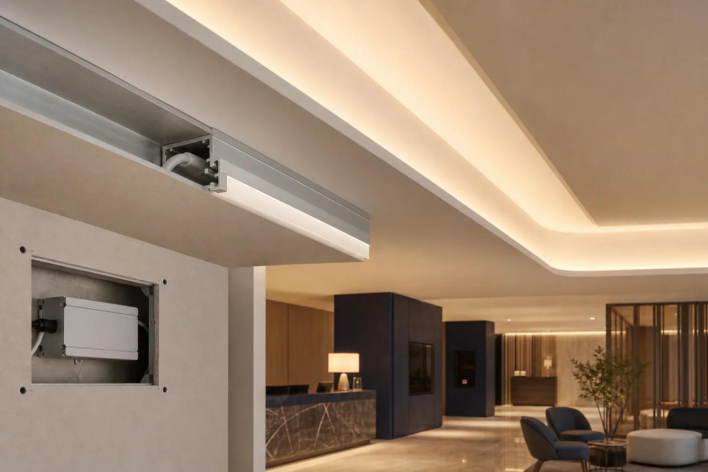
The short answer
For many commercial coves, a 24V COB strip in a suitable aluminum profile is a practical starting point because it can create a smooth line and reduce current compared with an equivalent 12V load. It is not automatically the best answer. A high-density SMD strip may be preferable when output, efficiency, serviceability or a specific optical result matters more than a continuous emitting surface.
Choose from the finished effect backward: target brightness on the ceiling or wall, viewing distance, cove dimensions, CCT and CRI, run lengths, feed access, dimming, ambient temperature and maintenance plan. Approve a full-size mock-up before ordering the project quantity.
Start with the cove and the required effect
Ask the designer or contractor to define what the cove must do:
- soft decorative glow or meaningful ambient illumination;
- ceiling wash, wall wash or a visible linear line;
- uniform effect across corners and long runs;
- fixed white, tunable white or dynamic color;
- minimum dim level and fade behavior;
- no visible dots from normal viewing positions;
- integration with room controls or building automation.
A strip cannot be selected reliably from room area alone. The distance from strip to reflecting surface, cove lip, aiming direction, surface color and diffuser can change the result. Dark timber absorbs more light than white plaster. A narrow cove can reveal hot spots that disappear in a deeper detail.
If the project has a lux target, calculate and verify it at the relevant surfaces. “14W per meter” describes electrical input, not delivered illuminance.
COB or SMD for cove lighting?
Choose COB when the light source may be seen
COB places many chips under a continuous phosphor layer, producing a smooth emitting line. It is useful for shallow profiles, reflective surfaces and coves where occupants can see the source from stairs, balconies or low viewing angles.
The COB LED strip range includes different widths, densities, voltages, powers and constructions. The COB label does not remove the need to compare output, color consistency, heat and maximum run.
Choose SMD when the complete optical system meets the requirement
A high-density SMD strip behind a sufficiently deep, well-diffused profile can also produce a smooth cove effect. SMD may offer a broader choice of power levels, package types and special functions. If the source is fully concealed and only reflected light is visible, package dots may not matter.
Compare a suitable SMD strip and COB sample in the real cove. Do not judge them uncovered on a table. The COB vs SMD commercial comparison explains the wider trade-offs.
Voltage and feed layout decide whether the cove stays uniform
For low-voltage commercial coves, 24V is often preferred over 12V because the same wattage draws half the current. That can reduce cable loss and simplify longer branches, but it does not eliminate voltage drop.
Before procurement, divide the cove into electrical sections and record:
- powered length per branch;
- watts per meter and total branch load;
- driver location and accessible service route;
- one-way cable distance from driver to feed;
- cable conductor size;
- single-end, dual-end or intermediate feed points;
- controller and amplifier position;
- voltage-drop limit agreed for the project.
Do not connect a long decorative perimeter as one continuous daisy chain just because the reel can be physically joined. The far end may dim or shift color. Use the calculation steps in the voltage-drop guide.
AC220V strip can support long runs in appropriate projects, but it is a mains-voltage system with different cut intervals, accessories, protection and installation requirements. It should not be selected only to avoid planning driver locations. Qualified electrical design and destination-market rules apply.
The profile is part of the product system
An aluminum profile provides mounting, heat spreading, mechanical protection and diffuser support. Check that:
- internal width accepts the PCB and soldered cable entry;
- depth and diffuser produce the approved dot-free result;
- the profile can be fixed continuously without twisting;
- corners and joints do not create bright or dark gaps;
- air around the assembly matches the thermal assumptions;
- the strip and profile remain accessible where replacement is expected.
Do not hide a high-power strip in an unventilated plaster pocket and approve it from a short open-air sample. Test the intended powered length in the actual profile after thermal stabilization. The strip manufacturer can state product data, but the ceiling designer controls much of the installed thermal environment.
For dry interior coves, adding a waterproof sleeve without an exposure need can make the strip larger and change heat transfer, bending and optical appearance. Select IP construction from actual exposure, cleaning and condensation risk.
Dimming and maintenance must be designed before the ceiling closes
Confirm whether the project uses PWM, 0–10V, DALI, phase-cut or another control architecture. The strip, driver and controller must be compatible. Test full output, the minimum required dim level, fade transitions and restart behavior with production-intent equipment. The LED strip dimming guide provides a compatibility checklist.
Keep drivers and control gear in ventilated, accessible locations permitted by the electrical design. Mark which driver serves each cove section. Leave a practical route to replace a strip, connector or driver without demolishing finished work.
For hotels, serviceability affects dozens or hundreds of repeated rooms. Standardize branch lengths, connector orientation, profile, driver, CCT and spare-part identification. One successful lobby mock-up does not automatically approve a different guest-room detail.
What the full-size mock-up should prove
Build the most difficult representative section, including a corner and the longest planned feed where possible. Inspect it from every normal viewing position.
| Check | Approval evidence |
|---|---|
| Brightness | Lux or agreed visual result at relevant surfaces |
| Uniformity | No unacceptable feed-end, far-end or corner difference |
| Dot visibility | Acceptable through the actual profile and cove geometry |
| Color | Approved CCT, CRI and adjacent-run consistency |
| Dimming | Stable operation across the required range |
| Temperature | Recorded after stabilization in the intended assembly |
| Maintenance | Driver and strip can be identified and accessed |
| Finish coordination | No glare, reflections, shadows or visible cables |
Photograph the approved mock-up, identify every component and retain the powered strip sample. Use the sample approval process to connect the mock-up to the purchase order.
Cove-lighting RFQ checklist
- plan, section and cove dimensions;
- total length and longest electrical branch;
- decorative or illuminance target;
- COB, SMD or open-to-recommendation status;
- voltage, CCT, CRI and color tolerance;
- fixed white, tunable white or RGB requirement;
- profile and diffuser drawing;
- dimming and control protocol;
- driver locations and cable distances;
- IP or environmental conditions;
- destination market and document requirements;
- mock-up quantity and production schedule.
Send the drawing rather than only the total meters through the quotation form. A useful cove-lighting quotation should show the proposed strip model, compatible system components and the assumptions that still require project confirmation.
Catalog & Sourcing Note
This article is prepared from our current product catalog and B2B specification workflow. Electrical, waterproofing and installation requirements vary by model and market, so confirm the final specification and approved sample before ordering.
Discuss Your Specification